
Welding equipment and welding method

A welding device and welding wire technology, applied in welding equipment, welding equipment, tin feeding devices, etc., can solve problems such as poor appearance, errors, and winding traces

Inactive Publication Date: 2010-03-31
TOYOTA JIDOSHA KK
View PDF1 Cites 7 Cited by
  • Summary
  • Abstract
  • Description
  • Claims
  • Application Information

AI Technical Summary

Problems solved by technology

[0007] However, as far as the technology disclosed in Patent Document 1 of the above-mentioned prior art is concerned, Figure 13 As shown, since generally the filler wire F' is unwound from the state wound on the drum and then sent to the wire supply unit 2', there are many cases of winding traces, and in the vertical direction relative to the joining object W' (refer to Figure 13 (A) arrow), horizontal (left and right) direction (refer to Figure 13 Arrow in (B)) may bend between the contact end 20' and the joining partner W' due to the contact of the filler wire F' with the joining partner W' when forcibly pressing, etc.
Therefore, even if the filler wire F' is brought into contact with the joining object W', there is a problem that an error occurs due to bending of the filler wire F' that occurs between the welding torch, the wire supply unit 2', and the welding line Y', etc.
In addition, in Patent Document 1, since the filler wire F' is bent, the inner peripheral surface of the contact end 20' constituting the wire supply unit 2' is partially rubbed and worn, so there is a problem that the contact end 20' is consumed too quickly.
[0008] And, in the prior art mentioned above, in such as Figure 14 In the shown mechanical tracking mechanism 3' in which the contacts 30' are fixed in a state protruding from the wire supply unit 2' by a predetermined length, the welding wire Y is Figure 14 When the mid-height direction changes, when the tip of the contact 30' is brought into contact with the object W' to be joined, when the welding wire supply unit 2' is moved with a predetermined angle and distance relative to the welding site, there is energy. There is a problem that the irradiation position of the beam B' and the supply position of the filler wire F' deviate, etc., and in order to avoid this phenomenon, there is a problem that the welding line Y' of the joining object W' that can be welded is limited, etc.
[0009] and, if Figure 9 (b), Figure 11 and Figure 12 As shown, when a gap S is generated between the joint object W due to a forming error, etc., the weld C is dented or perforated, and welding defects such as poor appearance and insufficient joint strength occur. However, in the prior art, there is no way to correct the generated Countermeasures for Gap

Method used


Image

  • Welding equipment and welding method
  • Welding equipment and welding method
  • Welding equipment and welding method

Examples


Embodiment Construction

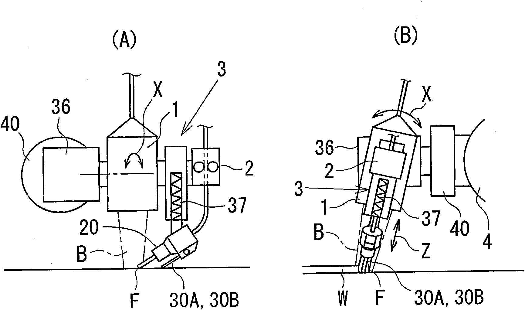
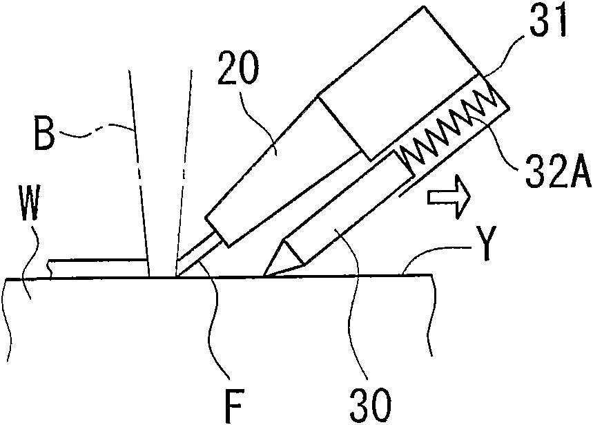
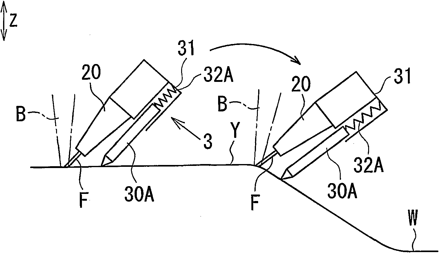
[0062] First, according to Figure 1 to Figure 4 , the first embodiment of the welding device of the present invention will be described in detail.

[0063] The welding device of the present invention generally includes: a welding torch 1, which imparts heat energy to the welding site; a welding wire supply unit 2, which supplies filler wire F to the welding site; and a tracking unit 3, which controls the movement trajectory of the welding torch 1 and the welding wire supply unit 2 Follow the welding line Y; the tracking unit 3 has a contact 30A or 30B, and the contact 30A or 30B is arranged in a manner that can advance and retreat or can rotate, and elastically contacts the joint object W; the filler wire is supplied to the welding site by the welding wire supply unit 2 F, and the heat energy is given by the welding torch 1, and at the same time, the contact 30A or 30B of the tracking unit 3 is elastically contacted with the object W to be joined, so that the welding torch 1 ...


PUM


Abstract

Welding equipment includes a torch for irradiating a laser beam (B), wire feeding means (2) for feeding a filler wire (F), and a tracking means (3) for controlling the moving tracks of the torch (1) and the wire feeding means (2) to make a welding line (Y) copy them. The tracking means (3) has a contactor (30A) provided to freely advance / retract for making contact with a joint object (W) resiliently. The joint objects (W) are jointed mutually by touching the contactor (30A) of the tracking means (3) resiliently to the joint object (W) while feeding the filler wire (F) to a welding portion andirradiating that portion with a laser beam (B), thereby moving the torch and the wire feeding means (2) to copy the welding line (Y).

Description

technical field [0001] The present invention relates to a welding device and a welding method, and more particularly relates to a welding torch which imparts heat energy to a welding site and a welding wire supply unit which supplies filler wire to the welding site, the welding wire is supplied to the welding site through the welding wire supply unit, and the welding wire is supplied by the welding torch. A welding device and a welding method in which the thermal energy of the welding part is moved along the welding line to join the joint objects with each other. [0002] Here, the welding referred to herein refers to "brazing" in which the base material is not melted as much as possible, in addition to the case where the base material is melted. Background technique [0003] In order to join objects to be joined to each other, a technique of welding by supplying a filler wire from a wire supply unit and applying heat energy to a welded portion by a welding torch has been wi...

Claims


Application Information

Patent Timeline
Patent Type & Authority Applications(China)
IPC IPC(8): B23K26/20B23K9/12B23K9/127B23K3/06B23K15/00B23K26/21
CPCB23K9/1278B23K26/147B23K26/045B23K26/044
Inventor 内田圭亮西尾匡弘大野政喜宫岛宏丹沢雅树三方博成富士本博纪井畑伸士
Owner TOYOTA JIDOSHA KK
Learn More