Up-conversion luminescence infrared laser display screen, manufacture method thereof and application thereof

An infrared laser and display technology, which is applied to TVs, instruments, and parts of color TVs, etc., can solve the problems of difficult mass production of laser TVs, complex laser structures, and high costs, so as to save development costs and speed up production. The speed of industrialization and the effect of reducing production costs

Inactive Publication Date: 2010-03-17
曹望和
View PDF0 Cites 12 Cited by
  • Summary
  • Abstract
  • Description
  • Claims
  • Application Information

AI Technical Summary

Problems solved by technology

This kind of laser has complex structure and high process difficulty. Its cost accounts for about 80% of the total cost of laser TV, which is the key factor, so the cost naturally remains high; the second is the high cost of the scanner, which is a secondary factor, because as long as the mass production cost The third is that it adopts brand-new technology, and a brand-new production line must be established in order to produce it. In addition, it is non-standard research and development internationally, and the same is true in China.
In short, laser TVs are difficult to mass-produce, especially the red, green, and blue three-color laser sources used. Except for red light, there are currently semiconductor devices. When will green and blue semiconductor devices appear? Internationally, there is still no certainty

Method used


Image

  • Up-conversion luminescence infrared laser display screen, manufacture method thereof and application thereof
  • Up-conversion luminescence infrared laser display screen, manufacture method thereof and application thereof
  • Up-conversion luminescence infrared laser display screen, manufacture method thereof and application thereof

Examples


Embodiment 1

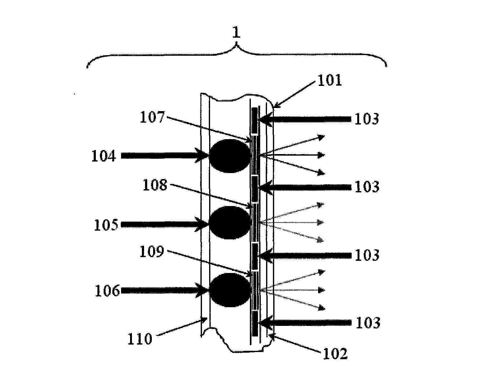
[0033] Such as figure 1 As shown, the manufacturing method 1 of the up-conversion luminescent infrared laser display screen:

[0034] It includes the following steps: the first step is to coat or paste or glue or plate an optical film 102 with high visible light transmission and infrared light (0.8-1.5 μm) high reflection or high absorption on the inner surface of the infrared laser panel 101. The red (R), green (G) and blue (B) three-primary color infrared laser display screen is excited by 0.8-1.5μm LD infrared laser, and there will inevitably be R, G , B. The infrared laser light absorbed by the three primary color luminescent materials emits out of the screen, which is unsafe for human eyes. It is necessary to add an optical film 102 with high transparency of visible light, high reflection or high absorption of infrared light on the viewing side of the screen.

[0035] The second step is to prepare a black matrix 103 on the surface of the optical film 102 through photoli...

Embodiment 2

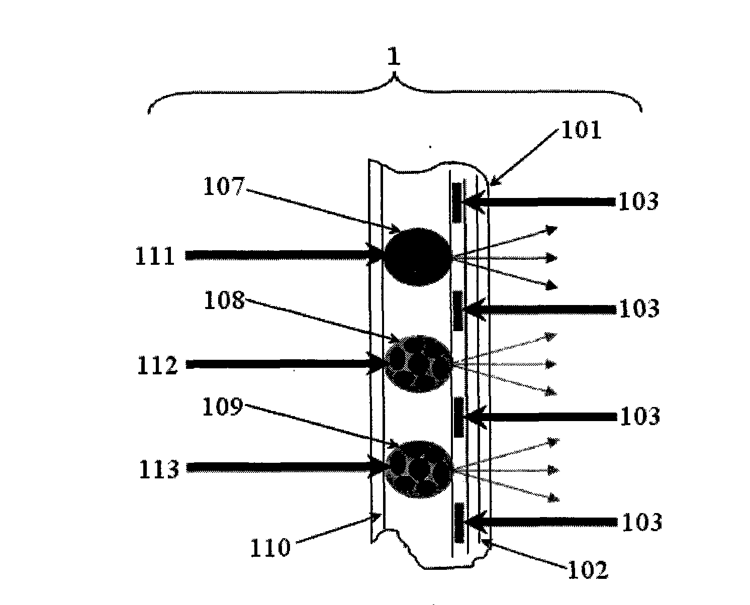
[0110] Manufacturing method 2 of up-conversion luminescent infrared laser display screen:

[0111] Such as figure 2 As shown, in order to simplify the screen-making process, the R, G, and B three-color light sources 104, 105, and 106 described in Embodiment 1 are uniformly mixed with the corresponding color filter films 107, 108, and 109. When G, B three primary color luminescent sources are mixed with the adhesive, corresponding R, G, B color filter films 107, 108, 109 are added at the same time to form the mixed coating paste of luminescent powder and color filter film respectively, and the additional R, G, B three-color luminescent powder with filter function 111, 112, 113. When the three-color light-emitting sources 111, 112, and 113 are used as the coating agent, the three-color pixel primitives are sequentially arranged on the hole array of the black matrix 103, so that there is no need to prepare additional color on the holes of the black matrix 103. filter film. Ex...

Embodiment 3

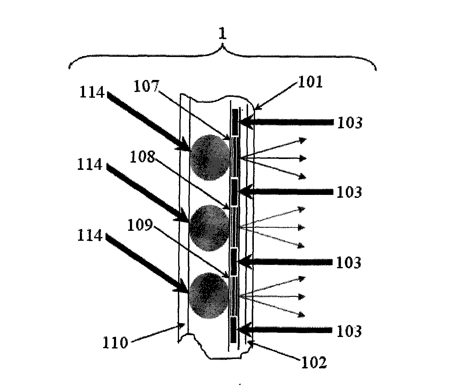
[0113] Manufacturing method 3 of up-conversion luminescent infrared laser display screen:

[0114] Such as image 3 , use the up-conversion white light powder that emits white light by mixing the three-color light source that emits R, G, and B, or the up-conversion white light powder that emits white light by mixing the two-color light source that emits R, G and the light source that emits B unit color Or the white-emitting up-conversion white powder 114 is directly synthesized from a compound to replace R, G, B three-color light-emitting sources 104, 105, 106 have a particle size of 0.5-10 μm. It is a white light source made by mixing the above-mentioned R, G, and B light sources in an appropriate proportion. Miscellaneous, R, G, B full-color luminescence is realized in the same matrix material, and white light is formed, and the CIE (x, y) of the white light emitted is close to the color coordinate value of equal energy white light (0.3333, 0.3333). Its preparation method...


PUM

PropertyMeasurementUnit
Particle sizeaaaaaaaaaa
Thicknessaaaaaaaaaa
Thicknessaaaaaaaaaa

Abstract

The invention belongs to the manufacture field of a laser television, in particular to the manufacture technical field of an infrared luminescence display screen and an infrared laser television. Aiming at the defects that the existing plasma and liquid crystal display have lower chroma and can not realize the application of large screen, and the existing laser television has high cost, the invention provides an up-conversion luminescence infrared laser display screen, manufacture method thereof and a display running system with the display screen. The display screen comprises an infrared laser faceplate; an optical film with visible light high transmission, infrared light high reflection or high absorption, which is manufactured on the infrared laser faceplate, black matrix manufactured on the optical film, a red, green and blue color light-filtering film manufactured on the hole of the black matrix, and a rare earth doping up-conversion red, green and blue trichromatic luminous source coated on the red, green and blue color light-filtering film. An infrared laser television system which consists of the display screen and the infrared laser display running system not only has high chroma, but also has lower cost than that of the laser television, thereby being a transition product between the liquid crystal display television and the laser television.

Description

technical field [0001] The invention belongs to the field of laser TV manufacturing, in particular to the technical field of manufacturing infrared laser display screens and infrared laser TVs. Background technique [0002] Since the advent of color displays, as we all know, what first appeared was cathode ray vacuum tube color displays (CRTs), followed by liquid crystal flat panel and plasma flat panel displays, and recently laser flat panel displays. Regardless of whether the display is a glass vacuum tube structure, a flat panel structure, or a laser structure, the shape of the screen is essentially determined by the properties of the three primary colors of red, green, and blue that display the color. At present, liquid crystal displays are widely used. The red, green, and blue colors used in liquid crystal displays are obtained from the white light behind the screen plus color filter films. Compared with CRTs, they are flat and light in weight. outstanding advantages. ...

Claims


Application Information

Patent Timeline
IPC IPC(8): G09F9/00H04N5/44
Inventor 曹望和
Owner 曹望和
Why Eureka
Try Eureka