
Vibration-reducing blasting construction method of air spring

A construction method and air spring technology, applied in blasting, excavation, infrastructure engineering, etc., can solve the problems of too much impact on building safety, failure to achieve blasting effect, and decline in rock destructive ability, so as to improve blasting efficiency and improve blasting performance. Effect, effect of increasing the range of action

Inactive Publication Date: 2010-03-17
CHINA CONSTR FIFTH ENG DIV CORP LTD +1
View PDF0 Cites 5 Cited by
  • Summary
  • Abstract
  • Description
  • Claims
  • Application Information

AI Technical Summary

Problems solved by technology

During blasting, due to the high instantaneous pressure and strong impact force generated by the explosives, the energy is directly transmitted through the rocks, causing strong vibrations on the surrounding ground and buildings, especially in densely built areas, and the resulting vibrations bring safety hazards to buildings
After part of the energy of the blasting is transformed into a vibration shock wave, the energy of the rock-breaking stress wave on the rock is reduced instead, and the ability to destroy the rock is reduced, so that the expected blasting effect cannot be achieved. If the amount of explosives is increased, the vibration generated by the blasting will be reduced. At the same time, it also increases significantly, which has a great impact on the safety of buildings, and the flying stones, dust and noise pollution generated by blasting also increase with the increase in the amount of explosives, which has a very serious impact on the surrounding environment.

Method used

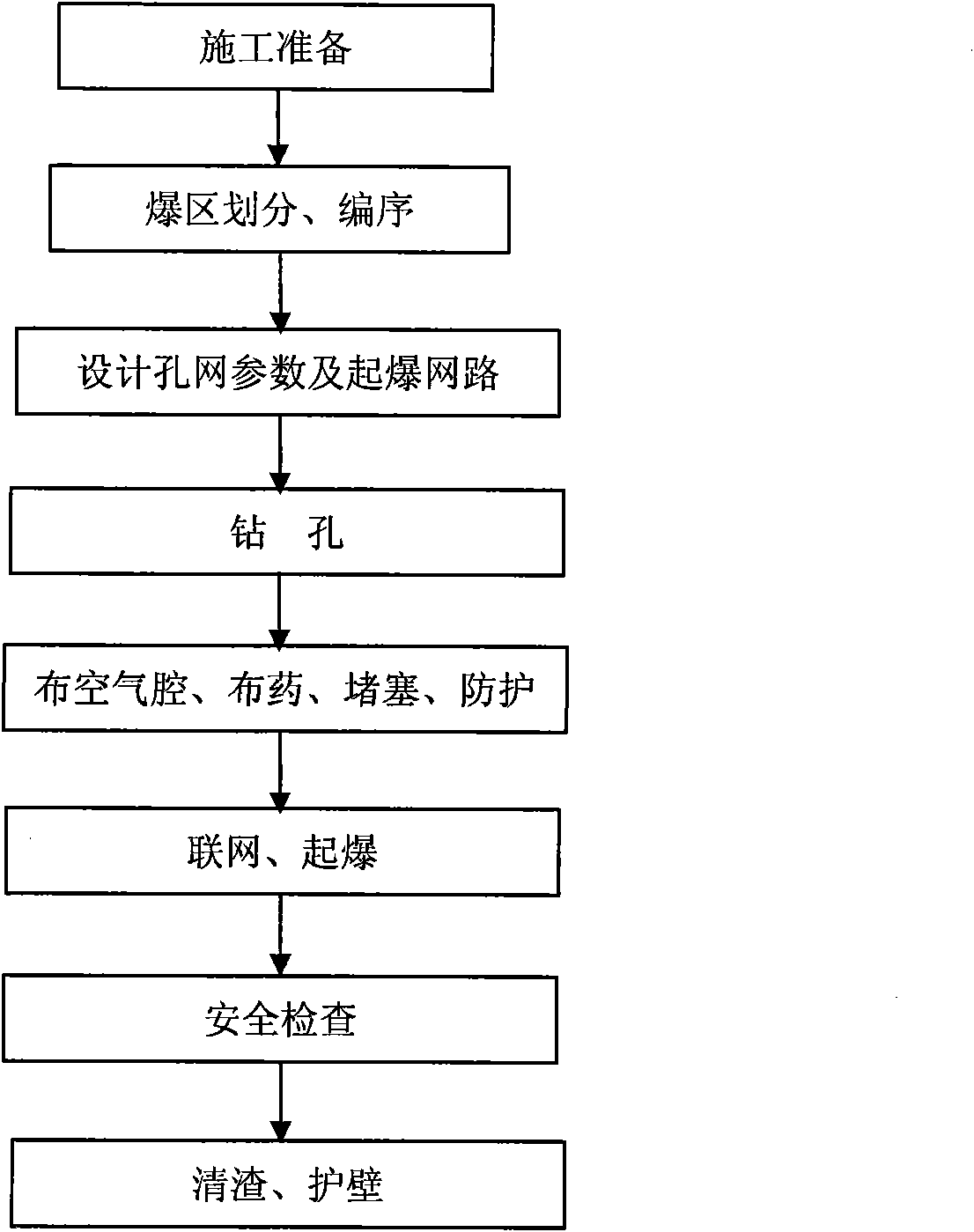
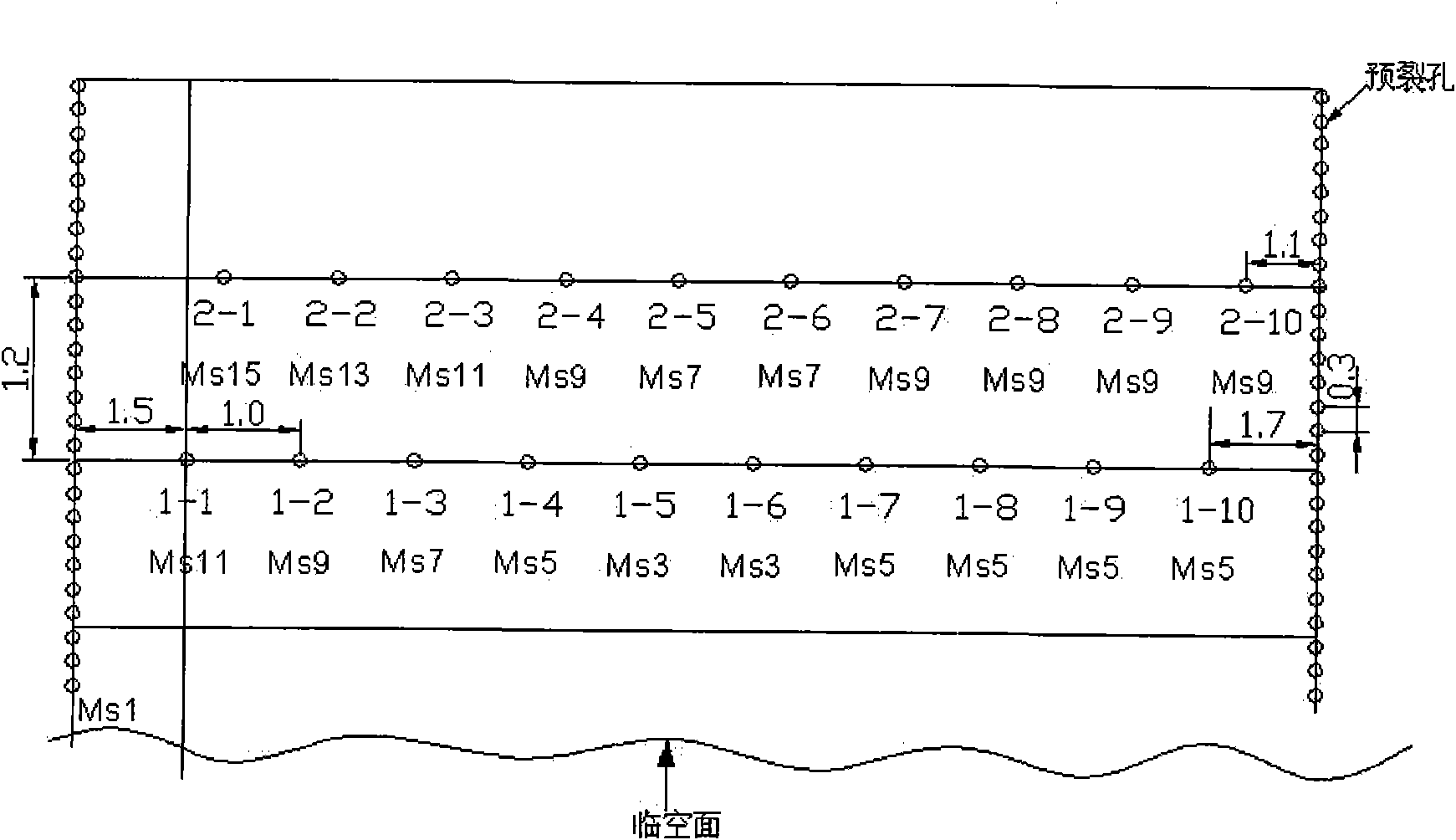

Image

  • Vibration-reducing blasting construction method of air spring
  • Vibration-reducing blasting construction method of air spring
  • Vibration-reducing blasting construction method of air spring

Examples


Embodiment Construction

[0035] The present invention will be further described below in conjunction with the accompanying drawings and specific embodiments.

[0036] The air spring damping blasting construction method of the present invention is suitable for rock-soil blasting in dense urban areas, various rock-soil blasting with strict requirements for protection facilities around blasting areas, local cutting blasting of large concrete blocks, and large-scale rock-soil blasting occasions.

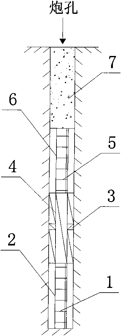
[0037] The construction method of the present invention is to design the hole network parameters and the detonation network in the divided blasting area, and to drill holes and fill explosives at the determined blast hole points; figure 1 As shown, its innovative point is that when charging the gun hole, the following steps are followed:

[0038] 1) After checking that the hole layout meets the design requirements, reserve an air cavity 1 at the bottom of the hole of 300mm to 500mm. The air cavity 1 at the botto...


PUM


Abstract

The invention relates to a vibration-reducing blasting construction method of an air spring, the parameters of a perforated mesh and a blasting initializing network are designed in a divided blastingregion, a hole is drilled in a determined blasting hole point and explosives are filled in the hole; and when the explosives are filled in a blasting hole, the operation is carried out according to the following steps: 1) reserving an air cavity at the bottom of the hole, wherein, the air cavity is formed by a cavity in a support body arranged at the bottom of the hole, and the support body is a hollow tubular structure with openings at two ends; 2) sequentially mounting a blasting initializing body and the explosives at the opening arranged at the upper end of the air cavity at the bottom ofthe hole, wherein, the blasting initializing body is connected with an external blasting initializing device through a lead wire; 3) further setting the air cavity at the upper end of the explosives,wherein, the air cavity is formed through the cavity in the support body; and 4) filling a blocking material in the blasting hole, wherein, the blocking material is used for filing gap in the periphery of the support body and the explosives and filling the blasting hole. The construction method has the advantages of small peak vibration during blasting, high safety, strong damage, high utilizationrate of energy and abilities of effectively controlling the blasting range and reducing the environmental pollution.

Description

technical field [0001] The invention belongs to the field of construction engineering, and in particular relates to an air spring damping blasting construction method used for foundation pit earthwork blasting. Background technique [0002] With the rapid development of urban construction, the utilization rate of land resources is also constantly improving. System planning to realize multi-functional and comprehensive large-scale buildings has gradually become the mainstream of urban construction. This will inevitably involve the excavation of deep foundation pits in urban high-density building complexes. project. With the current engineering technology in our country, blasting is still the main method for the excavation of a large number of rock foundation pits, especially in the narrow construction site and the building complex in the bustling commercial area, the vibration and noise caused by the excavation of the foundation pit are harmful The surrounding environment ha...

Claims


Application Information

Patent Timeline
Patent Type & Authority Applications(China)
IPC IPC(8): F42D3/04F42D1/00F42D1/08F42D1/22E02D17/02
Inventor 周永红彭小毛施富强王坚
Owner CHINA CONSTR FIFTH ENG DIV CORP LTD
Learn More