A master-controlled elastic support dry friction damper applied to aero-engine

A technology of dry friction damper and aero-engine, applied in spring/shock absorber, design features of spring/shock absorber, spring, etc., can solve the problem of affecting the friction force of friction plate, small radial stiffness, weakening dynamic friction force, etc. problem, to achieve parallel and uniform contact surface, improve radial stiffness, and ensure normal operation

Active Publication Date: 2022-03-15
NORTHWESTERN POLYTECHNICAL UNIV
View PDF7 Cites 0 Cited by
  • Summary
  • Abstract
  • Description
  • Claims
  • Application Information

AI Technical Summary

Problems solved by technology

[0007] 1. There is a gap in the radial direction of the installation of the static friction plate, and the radial stiffness is small and cannot be precisely designed
It is easy to cause poor contact parallelism between dynamic and static friction plates, which affects the damping effect
Moreover, when the amplitude of the moving friction plate, that is, the vibration at the fulcrum of the rotor is smaller than this gap, the static friction plate moves freely in the gap, there is no relative motion between the friction plates, and no damping occurs, so the effect of vibration reduction cannot be achieved
[0008] 2. The friction debris between the dynamic and static friction plates cannot be discharged
It mainly affects the continuous working effect of the damper. The accumulation of friction debris between the dynamic and static friction plates will weaken the dynamic friction force, affect the effect of the damper, and is not conducive to long-term use
[0009] 3. Lubricating oil easily enters the damper
If lubricating oil enters between the dynamic and static friction plates, it will inevitably affect the friction between the friction plates, which is not conducive to vibration reduction. Moreover, the wear debris may contaminate the lubricating oil and cause damage to the bearing.

Method used


Image

  • A master-controlled elastic support dry friction damper applied to aero-engine
  • A master-controlled elastic support dry friction damper applied to aero-engine
  • A master-controlled elastic support dry friction damper applied to aero-engine

Examples


Embodiment Construction

[0041] The embodiments described below by referring to the figures are exemplary and are intended to explain the present invention and should not be construed as limiting the present invention.

[0042] In describing the present invention, it should be understood that the terms "center", "longitudinal", "transverse", "length", "width", "thickness", "upper", "lower", "front", " Orientation indicated by rear, left, right, vertical, horizontal, top, bottom, inside, outside, clockwise, counterclockwise, etc. The positional relationship is based on the orientation or positional relationship shown in the drawings, which is only for the convenience of describing the present invention and simplifying the description, rather than indicating or implying that the referred device or element must have a specific orientation, be constructed and operated in a specific orientation, Therefore, it should not be construed as limiting the invention.

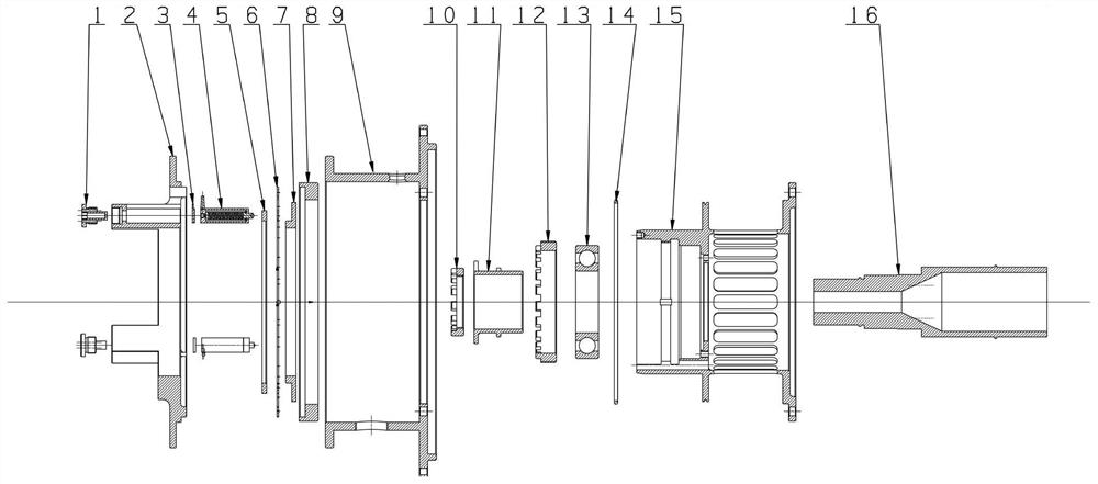
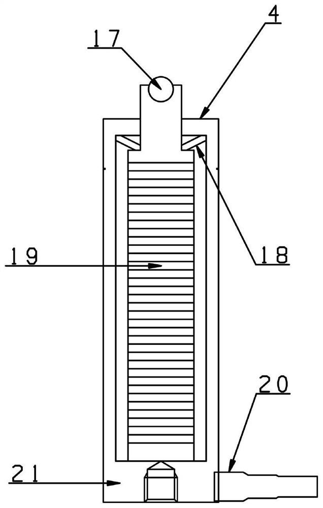
[0043] This example is a master-controlled s...


PUM


Abstract

The invention relates to a main-controlled spring-support dry friction damper applied to aero-engines, which belongs to the field of aero-engines; it includes elastic supports, dynamic friction plates, static friction plates, piezoelectric ceramic actuators, force transmission casings, and preload adjustment Bolt, damper installation cylinder, static friction plate fixing ring, static friction plate shrapnel, static friction plate shrapnel fixing ring, bearing inner bushing lock nut, bearing inner bushing, bearing outer ring lock nut and bearing; the elastic support passes through The inner bushing of the bearing and the bearing are coaxially installed on the rotating shaft, and the damper unit body is coaxially fixedly connected with the elastically supported flange through the force transmission casing; after introducing the static friction shrapnel into the damper unit body, the diameter can be significantly improved. To ensure the rigidity, and ensure the parallelism between the dynamic and static friction plates. In the vibration reduction experiment of the damper using shrapnel, the vibration peak value is reduced by more than 76.4% under the premise of compact structure.

Description

technical field [0001] The invention belongs to the field of aero-engines, and in particular relates to a main-control spring-support dry friction damper applied to aero-engines. Background technique [0002] The vibration reduction of rotor system is the key to solve the vibration problem of aeroengine. With the increase of the thrust-to-weight ratio of the engine within the operating speed range, there are several modes of the rotor system. During the operation, the rotor frequently crosses the critical speed. vibration effect. It is required that the damper can actively track the running state of the rotor, and change the parameters adaptively, so that the vibration in multiple modes within the working range can be controlled most effectively. Therefore, it is of great significance to realize the active vibration control of the rotor system, which is the basis for the development of high thrust-to-weight ratio engines. [0003] According to the characteristics of the s...

Claims


Application Information

Patent Timeline
Patent Type & Authority Patents(China)
IPC IPC(8): F16F15/129
CPCF16F15/1292F16F15/129F16F2230/30
Inventor 王四季廖明夫宁培杰陈自豪
Owner NORTHWESTERN POLYTECHNICAL UNIV
Why Eureka
Try Eureka