Drainage device

A drainage device and drainage tank technology, applied in the direction of condensed water discharge, etc., can solve the problems of backflow flute sound and unsolved water accumulation, and achieve the effect of preventing backflow of water accumulation and convenient installation

Inactive Publication Date: 2010-03-17
ZHEJIANG BAOYE CURTAIN WALL DECORATION
View PDF1 Cites 13 Cited by
  • Summary
  • Abstract
  • Description
  • Claims
  • Application Information

AI Technical Summary

Problems solved by technology

But, this invention still does not solve outdoor wind force to cause stagnant water to pour back and produce flute sound problem

Method used


Image

  • Drainage device
  • Drainage device
  • Drainage device

Examples


Embodiment 1

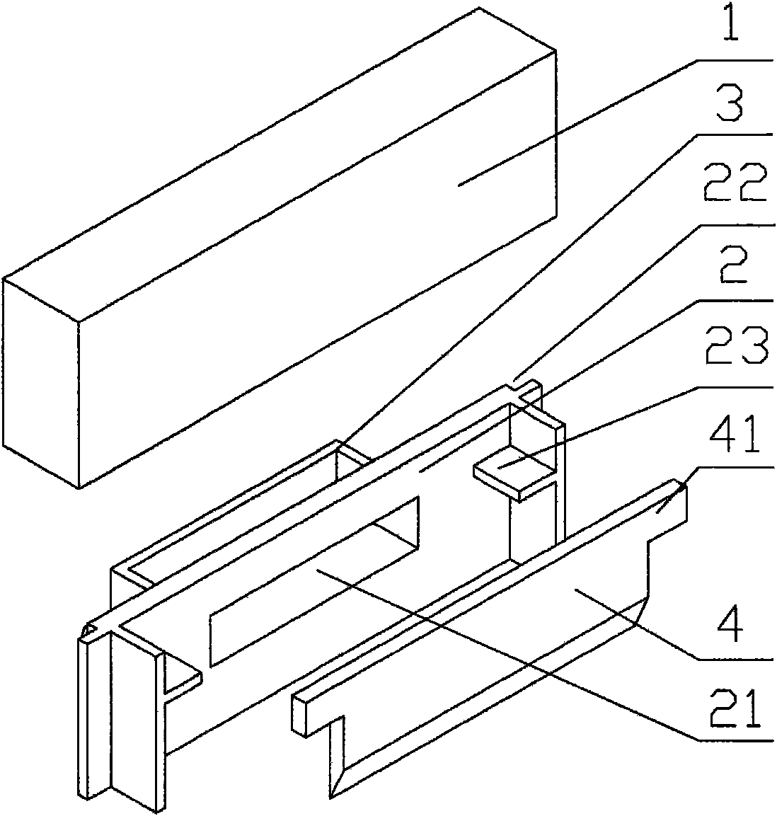
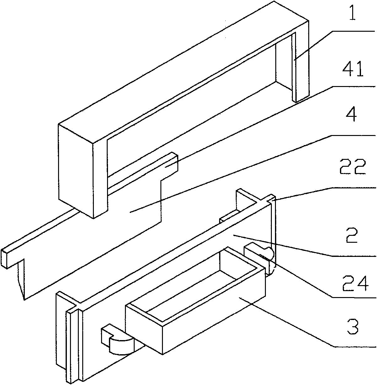
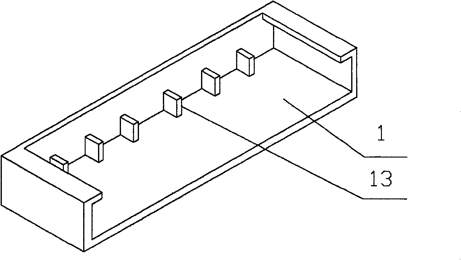
[0022] Such as figure 1 , figure 2 , image 3 As shown, the drainage device in this embodiment includes a housing 1, a mounting plate 2, a drainage groove 3, and a partition 4, wherein the housing 1 is a hollow structure with openings on the bottom and sides, and the mounting plate 2 is installed on the The casing 1, the casing 1 and the mounting plate 2 constitute the main body of the drainage device. The drain tank 3 is a hollow structure with top and side openings. The mounting plate 2 is connected to the drain tank 3 as a whole. The mounting plate 2 is provided with an opening 21 communicating with the side opening of the drain tank 3 . In addition, the top of the mounting plate 2 is also provided with a shelf 23, and the top of both sides of the partition 4 is provided with protrusions 41, and the partition 4 is suspended on the shelf 23 through the protrusions 41. The partition 4 can also be suspended by other means, such as in the case Through holes are set on both ...

Embodiment 2

[0026] This embodiment is a modification of Embodiment 1. Such as Figure 7 As shown, in order to better drain the water, the bottom of the gutter 3 is set as an inclined plane. In addition, the gutter 3 can be provided with multiple upward openings 31. For example, a sliding window is usually provided with a plurality of slide rails, and two or more grooves are formed between the slide rails. In this embodiment, the drainage device is provided with a plurality of slide rails. The opening 31 is upward, and a plurality of corresponding drainage holes are arranged at the bottom of the groove, and the drainage device can simultaneously discharge the accumulated water in all the grooves. In addition, the upper plane of the opening 31 can also be flush with the bottom of the groove, so that the accumulated water is not easy to overflow into the frame.


PUM


Abstract

The invention provides a drainage device for door and window frames. The drainage device mainbody is a hollow structure with an opening at the bottom; the side surface of the mainbody is provided witha drainage ditch that is provided with an opening and a drainage passage that face upwards; and the drainage passage of the drainage trough is communicated with the hollow interior of the drainage device mainbody. The mainbody hollow interior of the drainage device is also provided with a partition plate which is vertically hung on the top of the drainage device; and one surface of the bottom part of the partition plate, back to the drainage ditch, is an inclined surface that inclines towards the drainage ditch. Furthermore, the side surface of the mainbody of the drainage device also can beprovided with a buckling structure that is made of elastic material such as plastics or nylon PA66; during the installation process, the drainage device can be clamped at the corresponding opening ofthe window frame. The drainage device not only can effectively drain the accumulated water in a concave trough of the window frame, but also can prevent the problems of reverse pouring of accumulatedwater, splashing water, generating flute noise and the like caused by outdoor wind power; furthermore, the drainage device is extremely convenient to be installed on the door and window frames.

Description

technical field [0001] The invention relates to a door and window frame drainage device. Background technique [0002] At present, the door and window frame composed of channel profiles has many advantages compared with other structural forms of doors and windows, and has become the mainstream door and window frame structure of current buildings. The feature of this kind of door and window frame is that there are grooves on the upper surface of the lower horizontal frame. For example, in order to install wind braces or other structures on the frame of the casement window, the upper surface of the lower horizontal The door leaf, the window leaf or the screen window can be slid, and several upwardly convex sliding rails are arranged on the upper surface of the lower horizontal frame, and a groove structure is formed between these sliding rails. Due to the existence of the groove structure, one of the main problems of this kind of door and window frame is that the condensed wa...

Claims


Application Information

Patent Timeline
IPC IPC(8): E06B7/14
Inventor 王永江李智文
Owner ZHEJIANG BAOYE CURTAIN WALL DECORATION
Why Eureka
Try Eureka