


Quick Research
Generate reliable direction feasibility study reports for your R&D in just a few steps.

Technical Q&A
Discover and master advanced knowledge NOW. Basics, ideas, possibilities, all at once.

Find Solutions
As an expert in R&D theories, this can generate solutions to your technical problems instantly.

Evaluate Feasibility
Analyze your overall solution with one click, know your potential R&D risks in advance.

Monitor Landscape
Get weekly tech updates, stay abreast of the latest tech innovations and key insights.
Point-plane electrode system and method for micro-fluid drive by using the system
A point-surface electrode and surface electrode technology, applied in the field of microfluidic chips, can solve the problem that AC electrodynamics cannot explain the microfluidic flow phenomenon, and achieve the effects of obvious fluid driving speed, simple overall structure and low cost.
- Summary
- Abstract
- Description
- Claims
- Application Information
AI Technical Summary
Problems solved by technology
Method used
Image

Examples
specific Embodiment approach 1
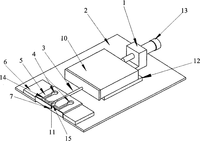
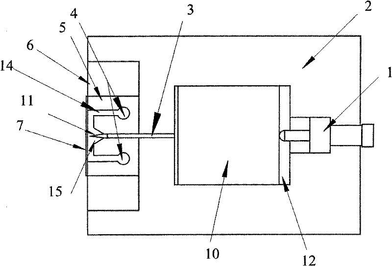
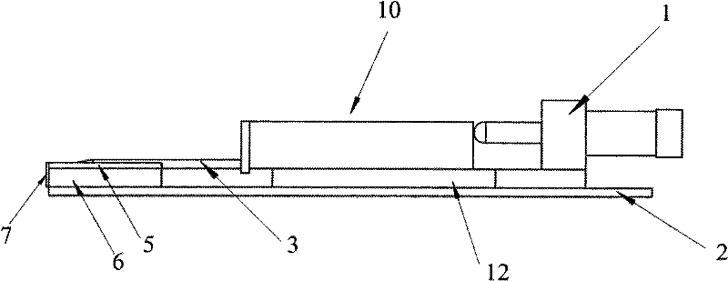
[0010] Specific implementation mode one: combine Figure 1-Figure 3 To illustrate this embodiment, the point-surface electrode system of this embodiment is composed of a spiral micrometer, a breadboard 2, a cylindrical metal rod 3, a polydimethylsiloxane plate 5, a surface electrode 7 and two glass slides 6 The screw micrometer is made up of a screw feeding device 1 and a micro-displacement platform 10, and one end of the cylindrical metal rod 3 is processed with a top 11, and the base 12 of the micro-displacement platform 10 and the upper end surface of the breadboard 2 Fixed connection, the lead screw 13 of the screw feed device 1 is in contact with one side end surface of the micro-displacement platform 10, and the polydimethylsiloxane plate 5 is fixed on the breadboard 2 and positioned on the side of the micro-displacement platform 10 Directly ahead, a glass slide 6 is arranged on the left side and the right side of the polydimethylsiloxane plate 5, and two slides 6 are at...
specific Embodiment approach 2
[0012] Specific implementation mode two: combination figure 1 and figure 2 To illustrate this embodiment, the two injection holes 4 of this embodiment are arranged symmetrically with respect to the central axis of the groove 15 , and the two microchannels 14 are arranged symmetrically with respect to the central axis of the groove 15 . It has good microfluidic flow effect and is convenient for testing. Others are the same as in the first embodiment.
specific Embodiment approach 3
[0013] Specific implementation mode three: combination figure 1 To describe this embodiment, the adjustment distance between the tip 11 of the cylindrical metal rod 3 and the surface electrode 7 of this embodiment is 0-5000 μm. Adjust different distances according to experimental conditions. Others are the same as in the first embodiment.
PUM
| Property | Measurement | Unit |
|---|---|---|
| diameter | aaaaa | aaaaa |
| diameter | aaaaa | aaaaa |
| thickness | aaaaa | aaaaa |
Abstract
Description
Claims
Application Information
 - R&D Engineer
- R&D Manager
- IP Professional
- Industry Leading Data Capabilities
- Powerful AI technology
- Patent DNA Extraction
Browse by: Latest US Patents, China's latest patents, Technical Efficacy Thesaurus, Application Domain, Technology Topic, Popular Technical Reports.
© 2024 PatSnap. All rights reserved.Legal|Privacy policy|Modern Slavery Act Transparency Statement|Sitemap|About US| Contact US: help@patsnap.com