
Push-pull device and method

A push-pull device and clamping device technology, applied to railway car body parts, locomotives, etc., can solve problems such as less than 100, long moving time of heavy objects, cumbersome operations, etc., to meet reliability and accuracy, and ensure rapid efficiency, satisfying the effect of simplicity

Inactive Publication Date: 2010-03-17
青岛天洋明机电有限公司
View PDF0 Cites 2 Cited by
  • Summary
  • Abstract
  • Description
  • Claims
  • Application Information

AI Technical Summary

Problems solved by technology

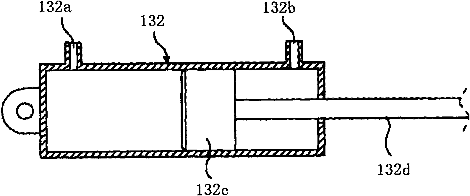
[0009] Therefore, when the power that the piston rod (132d) advances and pushes the slide rail (110) with the heavy object trolley (120) is 100, the force that occurs when the piston rod (132d) retreats does not reach 100, only half of it. Therefore it is not possible to move the trolley with the heavy load (120)
[0010] As a result, the conventional push-pull device (130) can only push the trolley (120) but cannot pull the trolley (120), and can only use other equipment such as winches, so the operation is cumbersome, inconvenient, and inefficient
[0011] The push-pull device in the past is that the clamping device (131) clamps the slide rail (110) while the hydraulic cylinder (132) piston rod pushes the trolley (120) or the upper structure on the slide rail (110), and the clamping device (131) releases the slide rail (110). The clamping of the rail (110) and the retreating action of the piston rod (132d) make the clamping device (131) advance along with the slide rail (110), and the trolley (120) cannot be moved with continuous driving force at this time.
[0012] Subsequently, when the clamping device (131) is re-used to clamp the slide rail (110) and the action piston rod of the hydraulic cylinder (132) pushes the dolly (120) on the slide rail (110), it needs to overcome the force equivalent to twice the dynamic friction force. Static friction requires the same force as the first time, not only it is not easy to move the trolley with heavy objects, but also because the moving time of the heavy objects required for the stop action and the acceleration and deceleration interval is too long, so it is moved to the floating dock on the sea surface, etc. It is necessary to deal with the ebb and flow of the tide, etc. It is exposed to the dangerous environment for too long, and it cannot move within the ideal tidal time (6 hours). There are many problems such as many restrictions and low efficiency.

Method used


Image

  • Push-pull device and method
  • Push-pull device and method
  • Push-pull device and method

Examples


Embodiment Construction

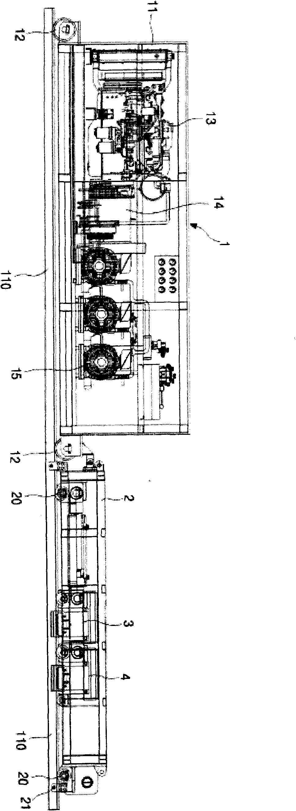
[0047] The invention is a push-pull device for transferring heavy objects. In detail, it is a push-pull device that makes the force of pushing or pulling the trolley with the heavy object on the slide rail the same, so that the trolley can transport the heavy object by pushing or pulling. In order to move the frame cover (2) with guide wheels (20) on the front and rear sides on the slide rail (110); the piston rod (3d) is installed in the same direction on the inside of the frame cover (2), and the majority of hydraulically actuated The push-pull hydraulic cylinder (3); the clamping device (4) that is installed on the rear side of the above-mentioned push-pull hydraulic cylinder (3) to fix or release the push-pull hydraulic cylinder (3) to the slide rail (110); the trolley moves the heavy object When it is necessary to run in the opposite direction, unlike other devices such as hoists in the past, only the push-pull device can achieve the effect of simplicity and efficiency of...


PUM


Abstract

The invention discloses a push-pull device and a method thereof. The push-pull device is a push-pull device for shifting weights, and comprises a frame, a guide wheel, a frame protecting cover, a piston rod and a push-pull hydraulic cylinder; the push-pull device can slide on a slide rail; one side inside the frame protecting cover is connected with the piston rod and the push-pull hydraulic cylinder in the same direction; and the push-pull hydraulic cylinder can perform once or times of hydraulic operation and is used for realizing the slide of the push-pull device on the slide rail. In the invention, the push force and the pull force of a trolley carried with weights are identical, so that the push-pull device for shifting weights can be realized by pushing or pulling the trolley, when needing reverse direction running in the process of shifting the weights by the trolley, only by using the push-pull device can the effects of simplicity and efficiency of operation be realized withoutneeding other equipments such as a winding engine and the like as usual. The invention ensures easiness and fastness of shifting of weights.

Description

technical field [0001] The invention relates to the technical field of a push-pull device for moving heavy objects, in particular to a push-pull device and method for moving a trolley with a heavy object in a push or pull manner by generating the same push and pull force on a slide rail . Background technique [0002] The general ship building methods include: using a dry dock to build a ship and pouring water into the dock to make the ship flood; after building a ship in sections on land, use a gantry crane to move the segmented ship to a floating dock at sea for assembly. The offshore construction method; the land construction method in which the entire ship is built on land and then transferred to barges and flooded. [0003] The above-mentioned land construction method is not like the dry dock shipbuilding method that does not need to dig the ground to build a dry dock first. Building an entire ship on land has the advantage of being easier to build than the offshore co...

Claims


Application Information

Patent Timeline
Patent Type & Authority Applications(China)
IPC IPC(8): B61C11/00B61B13/00
Inventor 李炳河
Owner 青岛天洋明机电有限公司
Learn More