
Control method of optimized running of combined cooling and power distributed energy supply system of micro gas turbine

A micro gas turbine, combined cooling and power technology, which is applied in the directions of gas turbine installations, machine operation, electrical program control, etc. problem, to achieve the effect of high primary energy utilization index

Active Publication Date: 2010-03-10
TIANJIN UNIV +2
View PDF0 Cites 53 Cited by
  • Summary
  • Abstract
  • Description
  • Claims
  • Application Information

AI Technical Summary

Problems solved by technology

[0006] 3) Micro gas turbines and supplementary combustion cooling and heating units form a joint supply system, which uses natural gas supplementary combustion to meet the cooling load demand of end users. Since cooling and heating are low-level energy products, the primary energy utilization efficiency of this system is relatively low. Low
[0008] 5) It does not take into account the impact of end-user cooling load and electricity load demand changes caused by seasonal changes on the optimal operation strategy of the combined cooling and power supply system

Method used


Image

  • Control method of optimized running of combined cooling and power distributed energy supply system of micro gas turbine
  • Control method of optimized running of combined cooling and power distributed energy supply system of micro gas turbine
  • Control method of optimized running of combined cooling and power distributed energy supply system of micro gas turbine

Examples


Embodiment Construction

[0027] The present invention will be described in detail below in conjunction with the accompanying drawings.

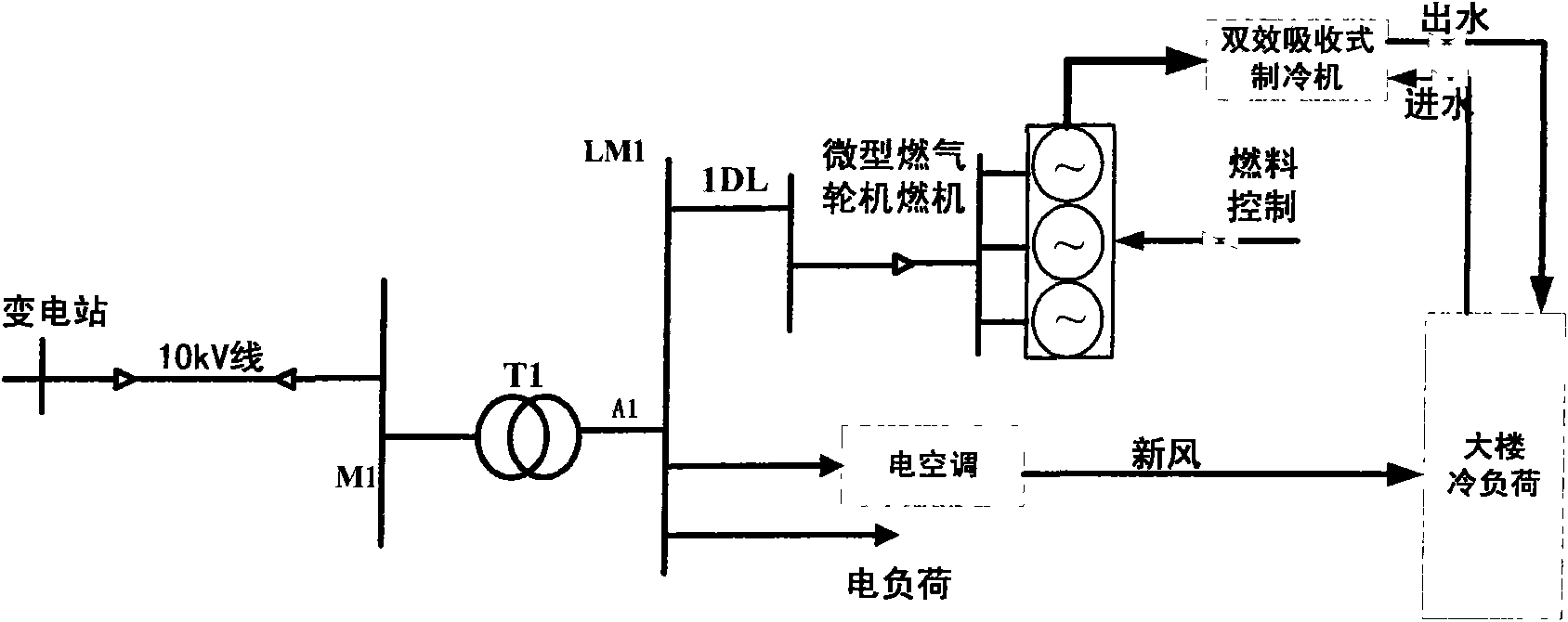
[0028] figure 1 The cooling and power supply system structure diagram of the end user is given. The electric loads of the end users, the central electric air conditioner and the micro-combustion unit are connected to the low-voltage bus. The combined cooling and power supply system adopts fan coil unit design to supply cooling to end users, and the central electric air conditioner adopts a full-air system. When the cogeneration system cannot meet the cooling load demand of end users, the cogeneration system can no longer supply cooling to some rooms equipped with electric air conditioners by controlling the cold water pipe valves in some rooms. Air conditioning is adequate.

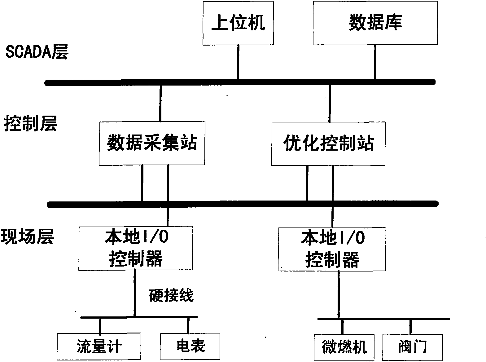
[0029]The entire optimization control system is composed of hardware and software: the hardware part is a distributed monitoring system, and the system structure is as follows: figure 2 As ...


PUM


Abstract

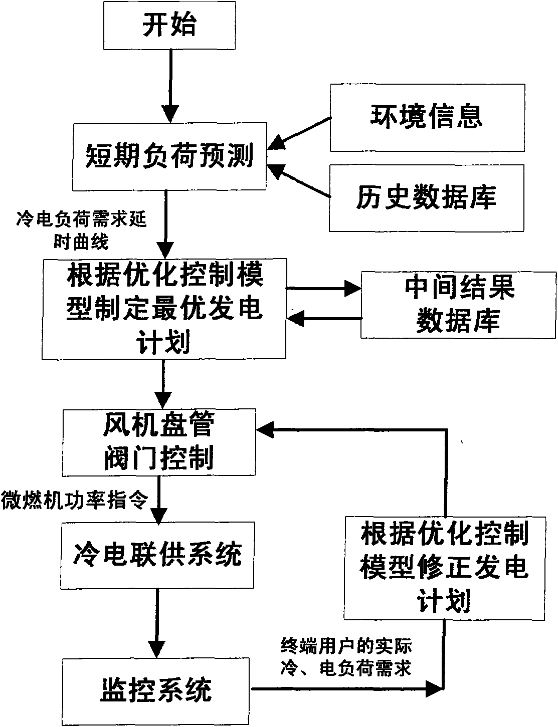
The invention belongs to the technical field of energy management of distributed generation energy supply systems of electric power systems. The control method comprises the following steps: before running a combined system on every workday, extracting history cooling load data and power load data of a terminal user from a historical data base and obtaining the delay variation curve of the coolingload and the power load of the terminal user during the whole workday by lone-term load predicting; according to load predicting results, working out the optimal generated output plan of the combinedsystem by adopting optimization control mathematical model; during the running of the combined system, carrying out optimization control calculation again by utilizing the terminal user real-time cooling and power load need obtained from the distributed control system, and modifying the generating capacity and the refrigerating capacity of the combined system. The invention utilizes a distributedmonitoring system to monitor the actual cooling and power load need of the terminal user and can modify the load forecasting result in real time and adjusting the respective controlled variable of the combined system.

Description

technical field [0001] The invention relates to an optimal operation control method of a distributed energy supply system for combined cooling and power supply of a micro gas turbine, and belongs to the technical field of energy management of a distributed power generation energy supply system of a power system. Background technique [0002] Micro gas turbine combined cooling and power distributed energy supply system refers to a comprehensive energy supply system with micro gas power generation device as the core equipment, which is suitable for direct construction in small and medium-sized end users, and provides power and cooling to users. The combined power generation system has the advantages of high energy cascade utilization efficiency, reliable power supply, good economic benefits, and environmental friendliness. The economic operation of the cogeneration system is not only related to the size of cooling load and electric load, but also related to factors such as whe...

Claims


Application Information

Patent Timeline
IPC IPC(8): G05B13/00G05B19/04F02C9/00F25B49/00F25B27/02
CPCY02A30/274
Inventor 郭力王成山吴小辰胡玉峰陈曦刘志超
Owner TIANJIN UNIV
Learn More