Lighting device

A lighting device and arm technology, which is applied to lighting devices, independent lighting devices, components of lighting devices, etc., can solve the problems of difficult operation of switches, larger packaging size, poor appearance, etc., and avoid fingertips. The effect of non-contact, easy switch operation

Inactive Publication Date: 2012-05-23
TWINBIRD CORP
View PDF7 Cites 0 Cited by
  • Summary
  • Abstract
  • Description
  • Claims
  • Application Information

AI Technical Summary

Problems solved by technology

In the case of contacting or pressing the above-mentioned switch, it is easier to operate the switch with the pulp of the finger, so it is necessary to twist the wrist near the lighting device to make the pulp of the finger touch the switch, and the operation of the switch is slightly difficult. The problem
On the other hand, in the lighting device such as Patent Document 2, since the above-mentioned switch is facingly arranged on the above-mentioned main body, the above-mentioned switch can be naturally operated with the pad of a finger, but the above-mentioned main body is electrically connected to the lampshade, so the above-mentioned main body and the flexible The condom cannot be separated
Therefore, there is a problem that the package size becomes large
In addition, in the lighting device such as Patent Document 3, since the above-mentioned switch is installed obliquely upward on the above-mentioned desk lamp mounting part, the above-mentioned switch can be naturally operated with the fingertips, but the above-mentioned desk lamp mounting part protrudes forward. So there is the problem of poor appearance

Method used


Image

  • Lighting device
  • Lighting device
  • Lighting device

Examples


Embodiment Construction

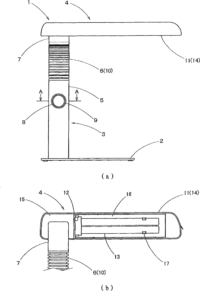
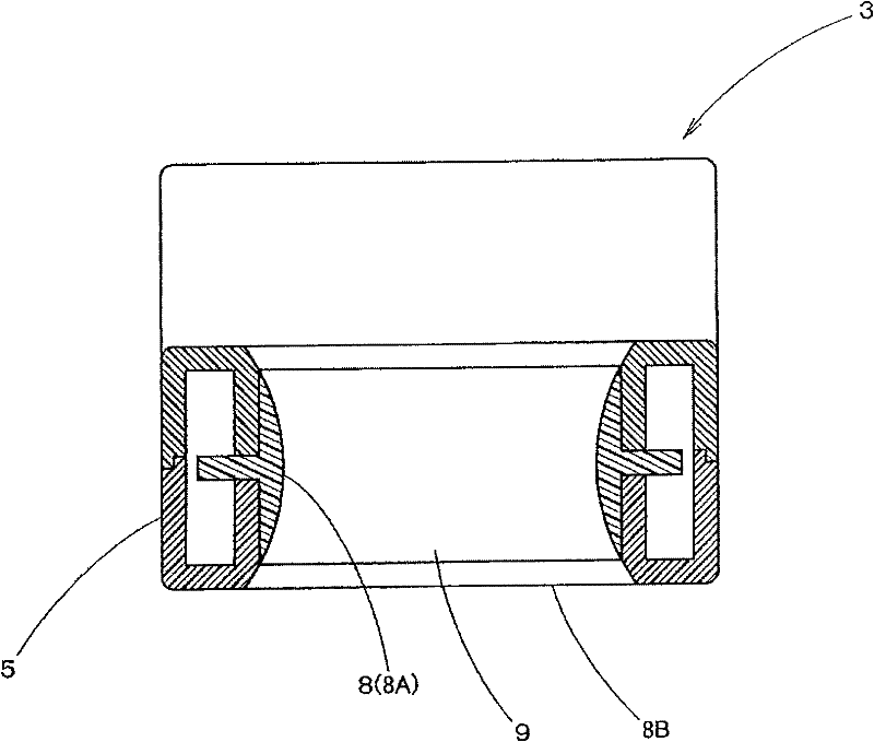
[0023] Below, based on figure 1 and figure 2 A first embodiment of the present invention will be described. Mark 1 is a radio lamp as a lighting device. This station light 1 is constituted by having a base 2 formed of a thick flat steel plate, an arm 3 , and a lamp 4 provided at the tip of the arm 3 . Furthermore, the arm portion 3 has a pillar portion 5 erected on the rear portion of the base portion 2 , a curved portion 6 provided on the upper portion of the pillar portion 5 , and a neck portion 7 provided at the front end of the curved portion 6 . In addition, a lighting circuit (not shown) for lighting a fluorescent lamp 13 to be described later is accommodated in the above-mentioned pillar portion 5 . Further, a hole 8 is formed through the pillar portion 5 in the front-rear direction, and an annular touch sensor 9 serving as a switch for the lighting circuit is provided on an inner peripheral surface 8A of the hole 8 . Moreover, the said hole part 8 is comprised so ...


PUM


Abstract

The present invention provides a lighting device which can be easily operated and need not thicken an arm portion than necessary. An electric table lamp (1) as a lighting device is provided with a lamp fixture (4) at the front end of the arm portion (3), a hole portion (8) is formed on a strut portion (5) for forming the arm portion and passes through along anterior-to-posterior, a contact mode sensor (9) is arranged at the inner peripheral surface (8A) of the hole portion and is used as a switch, thereby inserting fingers from an opening portion (8B) at the front of the hole portion, and operating the contact mode sensor in the hole portion, as as to lighten or quench the lamp fixture. In addition, the contact mode sensor can be natually touched by the finger pulp by arranging the contact mode sensor along the inner peripheral surface of the hole portion. Moreover, because the contact mode sensor is arranged on the hole portion, even the contact mode sensor is made into a construction not toward the positive surface, the strut portion need not be thickened than necessary.

Description

technical field [0001] The present invention relates to lighting devices, in particular to lighting devices such as radio lamps used on desks and the like. Background technique [0002] In the past, as this kind of lighting device, there is known following station light, and it has base, and the post part (corresponding to the arm part of the present invention) that is erected at the rear part of this base part, is provided with the curved top of this post part. (equivalent to the arm portion of the present invention) and a lamp provided at the front end of the curved portion, and a switch is provided on the front of the above-mentioned pillar portion (for example, refer to Patent Document 1). Moreover, the following task lighting device is also known, which has a main body and a lampshade (corresponding to the lamp of the present invention), and these parts are connected by a flexible sleeve (corresponding to the arm of the present invention), and the above-mentioned main b...

Claims


Application Information

Patent Timeline
Patent Type & Authority Patents(China)
IPC IPC(8): F21S6/00F21V23/04
Inventor 佐藤充幸
Owner TWINBIRD CORP
Why Eureka
Try Eureka