
K-shape slipping rail fastener

A rail and slip technology, applied in the field of railways, can solve the problems of not being able to ensure that the dynamic geometric dimensions meet the requirements, the requirements for the management value of the allowable deviations of the static geometric dimensions are getting higher and higher, and the railway operation requirements cannot be met.

Inactive Publication Date: 2010-03-03
EAST CHINA JIAOTONG UNIVERSITY
View PDF0 Cites 0 Cited by
  • Summary
  • Abstract
  • Description
  • Claims
  • Application Information

AI Technical Summary

Problems solved by technology

[0004] This kind of installation method of loose and tight fasteners can meet the requirements of use under normal-speed railway operating conditions due to low requirements for track geometric parameters. However, with the continuous increase of railway speed, the allowable deviation of the static geometric dimensions of the track The management value requirements are getting higher and higher. This kind of loose and tight installation method can no longer meet the requirements of railway operation, especially the track geometry of this installation method cannot be solved by normal maintenance methods, because after the static geometric size is satisfied, it will not Unable to ensure dynamic geometry meets requirements

Method used


Image

  • K-shape slipping rail fastener
  • K-shape slipping rail fastener
  • K-shape slipping rail fastener

Examples


Embodiment 1

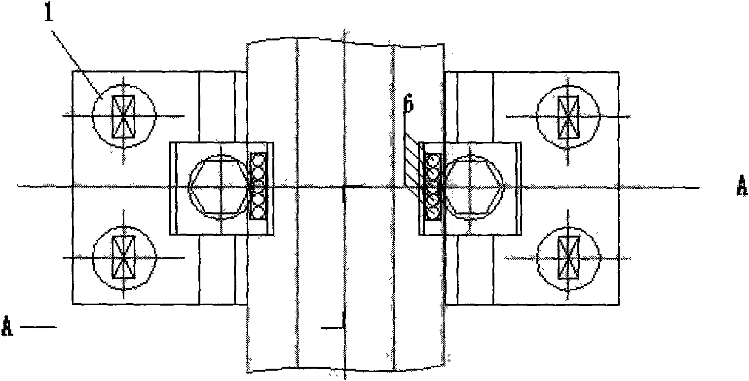
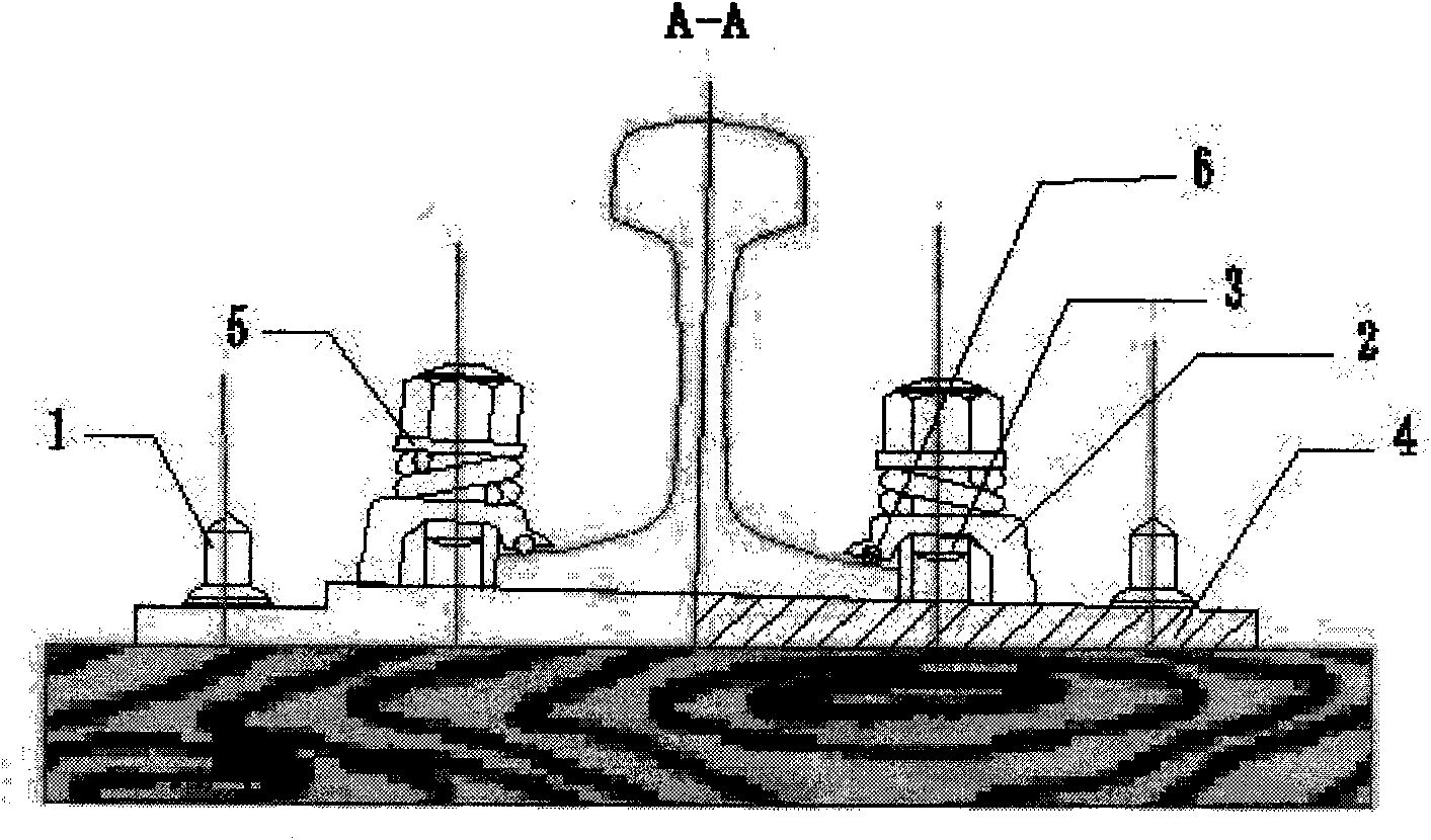
[0019] Embodiment 1: This embodiment is such as Figure 5 and Figure 6 As shown, a round hole groove is excavated at the flange (shorter side) of the buckle rail splint. The cross-sectional diameter of the round hole groove is 1-2mm larger than the diameter of the ball. The cross section of the round hole groove is a round platform larger than a semicircle. Fill the hole with some balls (such as Figure 5 ), after filling in the balls, the balls will expose 3-5mm from the flange surface of the buckle rail splint, but the balls will not fall out of the slots. drop.

Embodiment 2

[0020] Embodiment 2: This embodiment is such as Figure 7 and Figure 8 As shown, a slot hole is excavated at the flange (shorter side) of the buckle rail splint, and then a row of ball chains are inserted (the purpose is to isolate the balls), the balls are exposed 3-5mm, and the entrance is plugged with a prefabricated plastic cover , not only to ensure that the ball will not fall out, but also to make it roll freely on the rail.


PUM


Abstract

The invention relates to a K-shape slipping rail fastener which is composed of a rail-fastening plywood (2), an anchor bolt (3), a spring washer (5) and a cushion plate (4); the K-shape slipping railfastener is characterized in that: a round hole groove is arranged at the position of a flange of the rail-fastening plywood, a plurality of rolling balls (6) are filled in the hole groove, and the rolling balls are exposed to the flange surface of the rail-fastening plywood for 3-5mm, and the rail-fastening plywood tightly presses the steel rail by the rolling balls. The rolling balls can be combined in multiple ways or a row of rolling ball chain can be formed. The K-shape slipping rail fastener is suitable for the fixation of seamless track steel rails for paving bridges.

Description

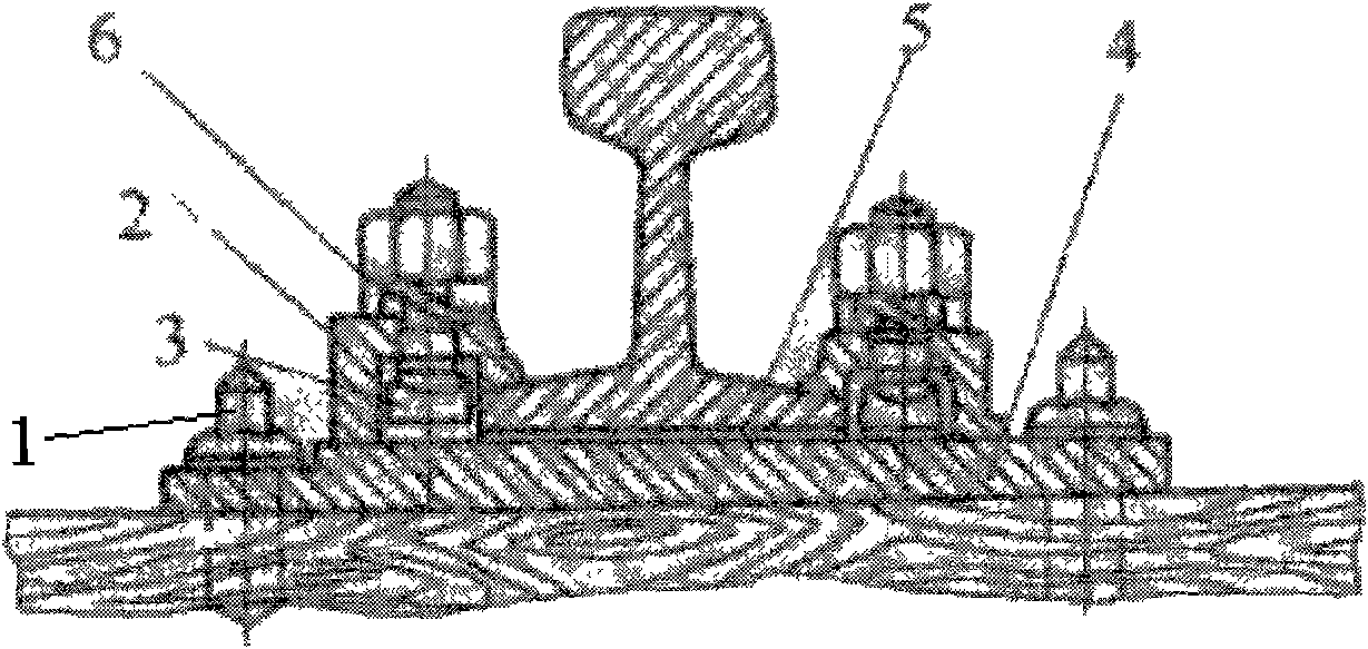
technical field [0001] The invention relates to a slidable rail fastener, which belongs to the technical field of railways. Background technique [0002] Traditional K-type fasteners such as figure 1 As shown, it is mainly used for integral ballast beds such as railway bridges, tunnels, and station lines. It has good elasticity and buckle performance, less maintenance, large backing plates, and firm connections, which can reduce mechanical wear of sleepers. [0003] Laying seamless lines on bridges has always been a major problem in the field of railway tracks, and the problem is more prominent on long bridges. The seamless line on the bridge is different from the seamless line on the roadbed and tunnel. Under the action of temperature and train load, the bridge produces longitudinal deflection and expansion deformation. The deformation of the beam body pulls the rail through the fastener. Huge additional stress is generated, and the fastener is subjected to huge tensile f...

Claims


Application Information

Patent Timeline
Patent Type & Authority Applications(China)
IPC IPC(8): E01B9/46
Inventor 李明华雷晓燕刘庆杰毛建红张鹏飞
Owner EAST CHINA JIAOTONG UNIVERSITY
Learn More