Power plant system and method for the operation thereof

A power station and equipment technology, applied in the field of power stations, can solve the problems of inverter power loss and inability to improve efficiency, and achieve the effect of high-efficiency emission value and low emission value

Active Publication Date: 2010-02-24
GENERAL ELECTRIC TECH GMBH
View PDF10 Cites 4 Cited by
  • Summary
  • Abstract
  • Description
  • Claims
  • Application Information

AI Technical Summary

Problems solved by technology

[0025] In known power station installations, the disadvantage of decoupling between the generator output and the grid by means of frequency converters with DC current and DC intermediate circuits is that the frequency converters cause significant power losses, which are In the turbine system and power plant equipment with a power greater than 100MW, the efficiency improvement partially obtained in this range cannot be realized

Method used


Image

  • Power plant system and method for the operation thereof
  • Power plant system and method for the operation thereof
  • Power plant system and method for the operation thereof

Examples


Embodiment Construction

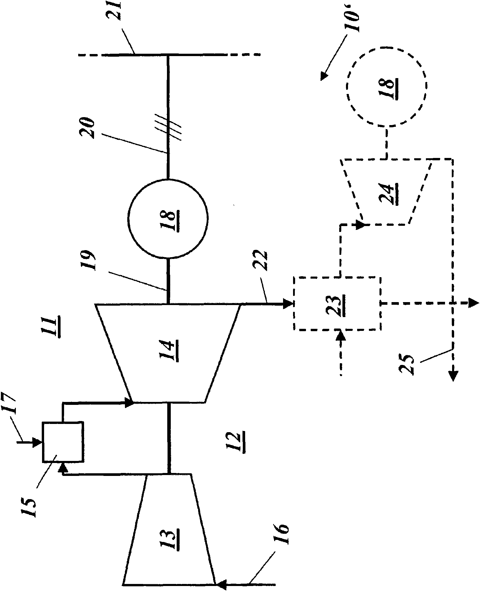
[0050] According to one embodiment of the present invention, in Figure 4 shows a power station installation with gas turbine and electronic decoupling in a very simplified circuit diagram. The power plant installation 10 comprises a gas turbine 12 with a compressor 13 and a continuous combustion plant, wherein a first combustion chamber 15 generates hot gas from a first fuel via a first fuel supply 17, which is expanded in a first turbine 14a It is then introduced into the second combustion chamber 15', where the passage of the second fuel through the second fuel supply 17' brings about a second increase in the temperature of the hot gas, which is then expanded in the second turbine 14b. Instead of a continuous combustion system, which is particularly effective in terms of efficiency, it is also possible to provide a single-stage combustion system. The rest of the equipment corresponds to the figure 2 or image 3 Components with the same reference numerals.

[0051] The g...


PUM


Abstract

The invention relates to a power plant system (10), comprising a turbine branch (11) made of a gas turbine (12) and a generator (18), which is directly driven by the gas turbine (12) and generates analternating current have an operating frequency, wherein the output of the generator is connected to a grid (21) having a predefined mains frequency. Between the generator (18) and the grid (21), an electronic decoupling device, or a variable electronic gear mechanism (27) is provided, which decouples the operating frequency from the mains frequency. In such a system, flexible operation with highefficiency is achieved in that the gas turbine (12) is configured for power greater than 100 MW, and that the electronic device (27) is a frequency converter in the form of a matrix converter.

Description

technical field [0001] The invention relates to the technical field of power stations. It relates to a power plant installation with electronic decoupling or electronic frequency conversion between a gas turbine and a grid, and a method for operating a power plant of this type. Background technique [0002] Large power plant installations with powers in the range of more than 100 MW generally have a fixed coupling between the (mechanical) rotational speed and frequency of the turbines, in which range the generators producing the current are powered by the gas turbines and / or the steam The turbines are driven and the electrical power generated is input into the grid at a predetermined frequency (eg 50 or 60 Hz). In this case, the output of the generator is connected to the grid at a fixed frequency via the grid connection, while the generator is driven by the turbine directly or rotationally coupled via a mechanical transmission. Such a scheme for power station equipment in...

Claims


Application Information

Patent Timeline
Patent Type & Authority Applications(China)
IPC IPC(8): F01D15/10F02C7/36F02C9/28H02K7/18F01K13/02F01D17/08
CPCF05B2270/1014F01D15/10F02C9/38F05D2270/05F05D2270/024F05B2270/106F05B2270/103F05D2270/08F02C9/28
Inventor J·霍夫曼T·梅恩德尔
Owner GENERAL ELECTRIC TECH GMBH
Why Eureka
Try Eureka