
Working machine

A technology of working machinery and action, applied in the direction of mechanical equipment, engine components, combustion engines, etc., can solve problems such as inability to cut off, achieve the effect of preventing voltage drop, realizing fuel consumption, and realizing the emission of carbon dioxide

Inactive Publication Date: 2012-06-27
KOMATSU LTD
View PDF6 Cites 0 Cited by
  • Summary
  • Abstract
  • Description
  • Claims
  • Application Information

AI Technical Summary

Problems solved by technology

However, the power supply system cannot be cut off in order to restart the engine when idling has stopped.

Method used


Image

  • Working machine
  • Working machine
  • Working machine

Examples


Embodiment

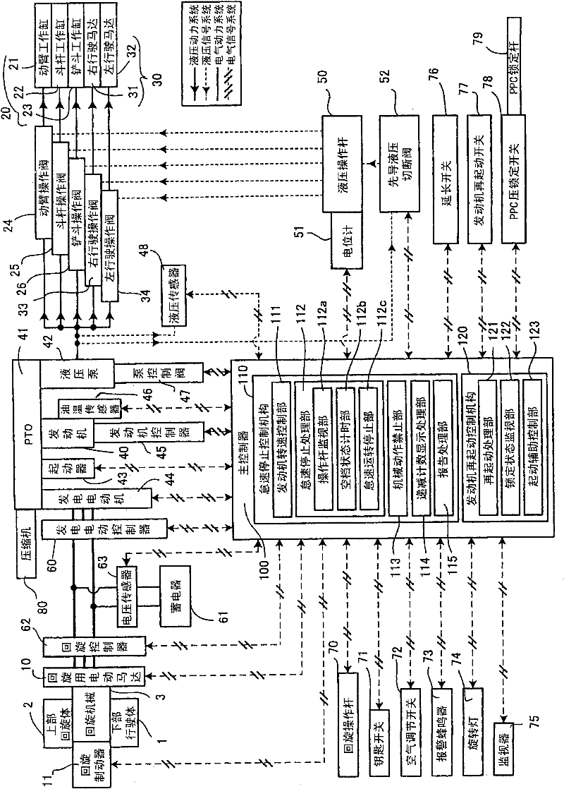
[0030] figure 1 It is a figure which shows the working machine of the embodiment of this invention. The work machine illustrated here is equipment for construction work such as a hydraulic excavator, and includes an undercarriage 1 and an upper revolving structure 2 . The undercarriage 1 travels on left and right crawler belts (not shown). The upper revolving structure 2 is disposed so as to be rotatable with respect to the undercarriage 1 via a revolving machine 3 constituted between the upper revolving structure 2 and the undercarriage 1 . Although not explicitly shown in the figure, the revolving machine 3 includes, for example, a revolving track and a pinion gear meshed with the revolving track, and the pinion is driven by the revolving electric motor 10 as an electric actuator, thereby enabling the upper revolving body 2 to face each other. When the undercarriage 1 is swung, the upper revolving structure 2 can be mechanically prevented from turning relative to the under...


PUM


Abstract

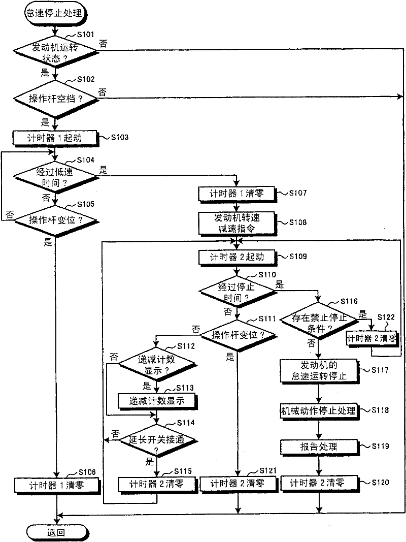
A working machine having hydraulic actuators (21, 22, 23, 31, 32), an electricity storage device (61) for storing electric power when a generator motor (44) performs power generation operation and supplying electric power when the generator motor (44) performs motor operation, and an electric motor (10) for rotation, wherein the hydraulic actuators (21, 22, 23, 31, 32) and the electric motor (10)for rotation are adapted to be operated by operation levers (50, 70). The working machine further has idle stop control means (110). When the neutral state of the operation levers (50, 70) continues for a predetermined stop time period with the engine (40) operated, the idle stop control means (110) stops the idle operation of the engine (40) if electricity having a voltage higher than or equal to a predetermined level is stored in at least the electricity storage device (61) and, at the same time, the idle stop control means (110) holds the electric motor (10) for rotation in an operation prohibited state.

Description

technical field [0001] The present invention relates to a working machine that causes a hydraulic actuator and an electric actuator to perform a desired operation by operating a control lever. Background technique [0002] Conventionally, in a working machine in which a hydraulic pump is driven by an engine and a hydraulic actuator for the working machine is operated using pressure oil discharged from the hydraulic pump, unnecessary idling of the engine is stopped. For example, Patent Document 1 discloses a configuration for stopping the idling of the engine when a predetermined time elapses without an operator in the cab. According to such a working machine, reduction in fuel consumption and reduction in the amount of emitted carbon dioxide can be achieved. [0003] Patent Document 1: Japanese Patent Laid-Open No. 2002-13425 [0004] In addition, currently, hybridization is being promoted in machine tools, and structures including electric actuators in addition to the abo...

Claims


Application Information

Patent Timeline
Patent Type & Authority Patents(China)
IPC IPC(8): E02F9/20E02F9/00
CPCE02F9/2025E02F9/2075E02F9/2246E02F9/123F02N11/0818F02N2011/0885F02N2200/063F02N2200/0802F02N2200/0812F02N2300/2011F02N11/0814Y02T10/40E02F9/20
Inventor 河口正森永淳井上宏昭
Owner KOMATSU LTD
Learn More