
Float glass melting furnace parallel connection waste heat power generation system

A float glass and waste heat power generation technology, which is applied in glass furnace equipment, glass manufacturing equipment, preheating, etc., can solve the problems of large fluctuation range of exhaust gas waste heat parameters, high one-time investment cost, and low waste heat utilization efficiency. Waste heat utilization rate, wide applicability, effect of improving power generation quality

Inactive Publication Date: 2010-02-03
成都南玻玻璃有限公司
View PDF0 Cites 11 Cited by
  • Summary
  • Abstract
  • Description
  • Claims
  • Application Information

AI Technical Summary

Problems solved by technology

[0008] The invention aims to solve the problems of low waste heat utilization efficiency, low power generation efficiency, poor system stability, high heat recovery cost, large fluctuation range of waste heat parameters of waste gas, serious environmental pollution, and high one-time investment cost in the waste heat utilization of traditional glass melting furnaces. Technical problem, to provide a float glass melting furnace parallel waste heat power generation system with high waste heat utilization rate, high power generation efficiency, good system stability, low heat recovery cost, environmental protection, and investment cost saving

Method used


Image

  • Float glass melting furnace parallel connection waste heat power generation system
  • Float glass melting furnace parallel connection waste heat power generation system
  • Float glass melting furnace parallel connection waste heat power generation system

Examples


Embodiment Construction

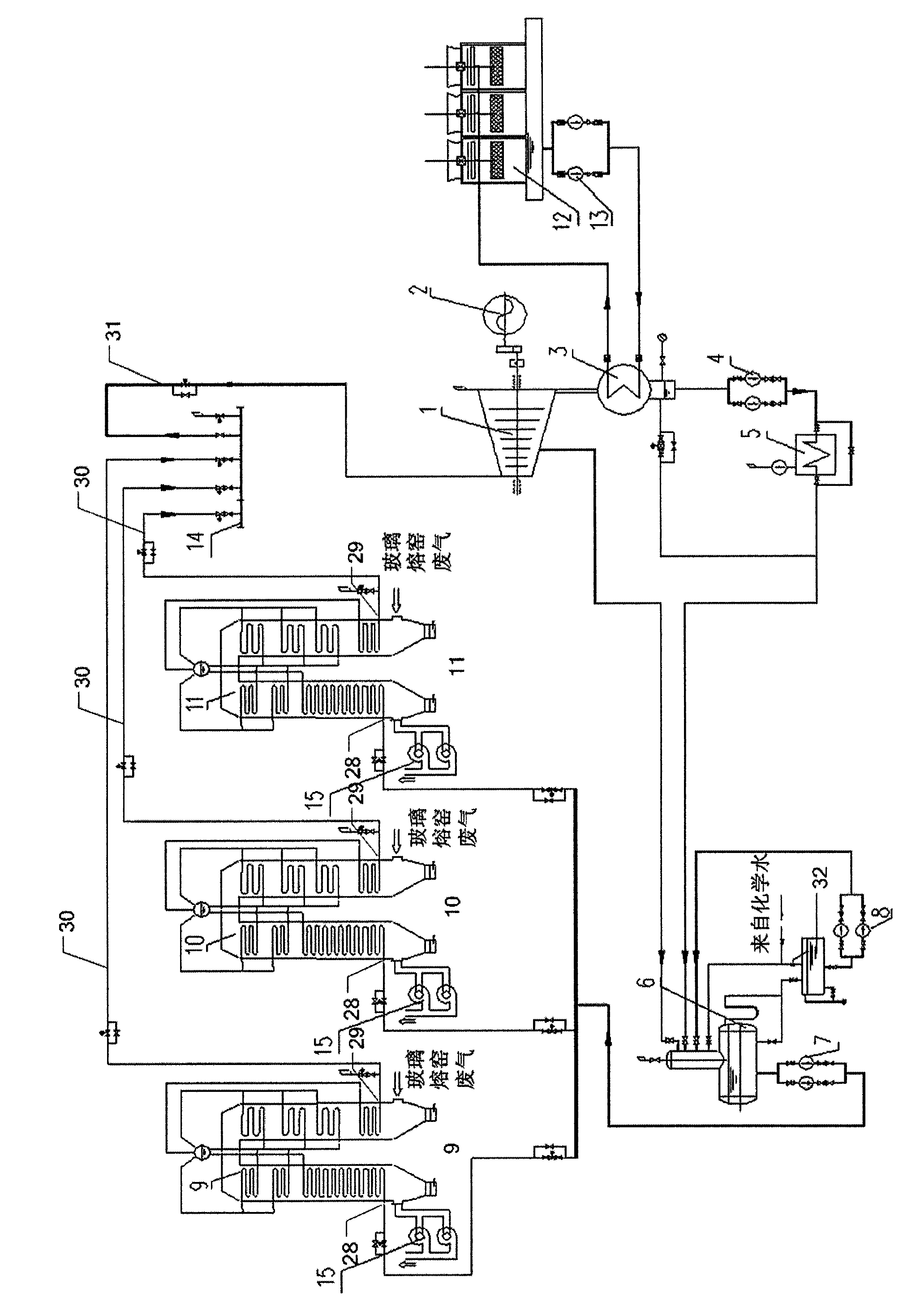
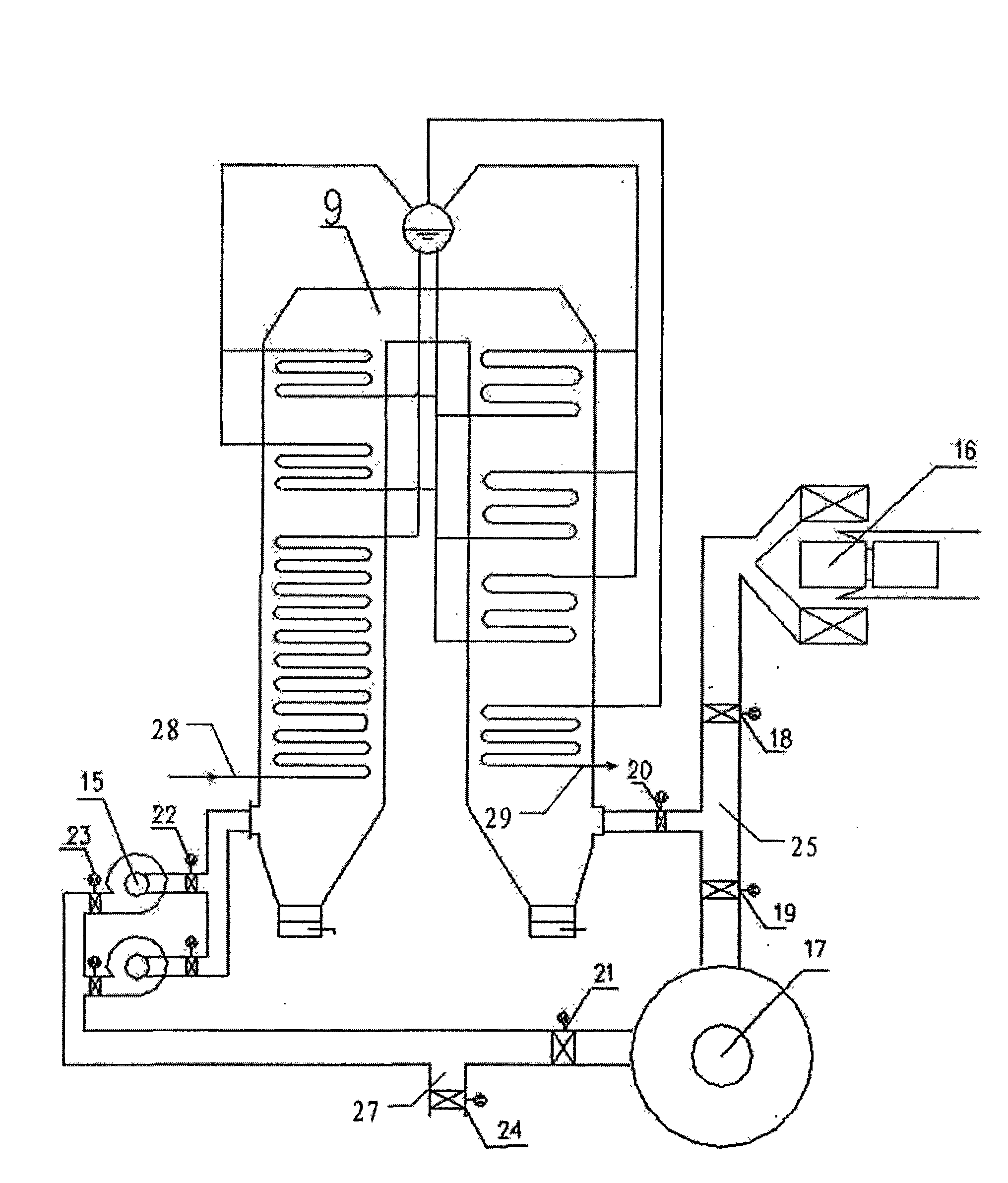
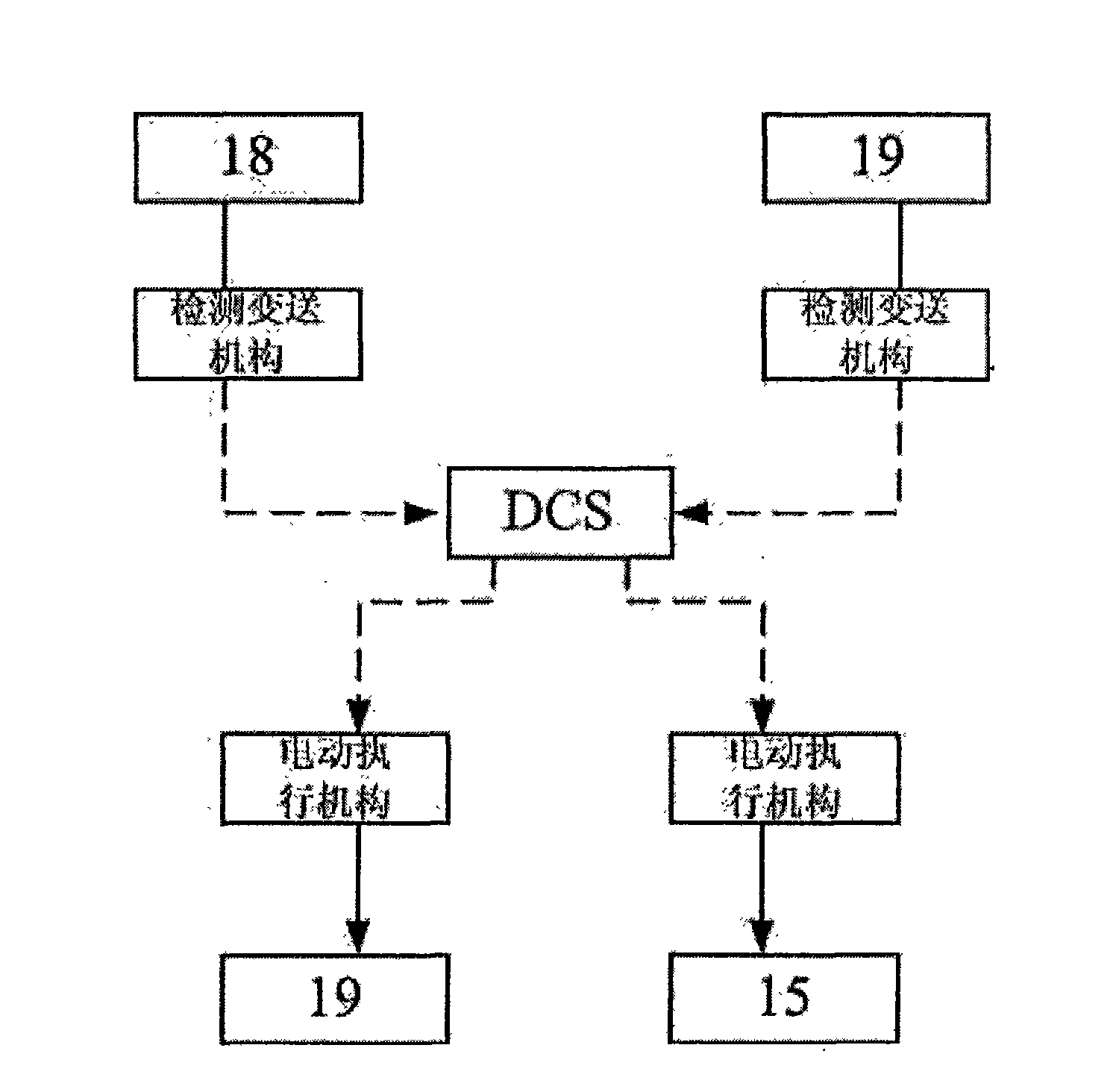
[0032] The detailed structure, application principle, function and effect of the present invention refer to the appendix Figure 1-3 It will be explained by the following embodiment.

[0033] The float glass melting furnace parallel waste heat power generation system of the present invention includes the flue gas discharge ports of three glass melting furnaces 16 connected to the flue gas inlets of the three parallel waste heat boilers through the outlet flues 25 in a one-to-one correspondence. The flue gas outlet is communicated with the chimney 17 . The waste heat boiler is a single-drum ∏ type waste heat boiler, that is, two vertical shaft flue gas passages are connected in a "∏" type arrangement.

[0034] The water outlet ends of the boiler feed pump 7 are respectively connected to the circulating water inlets 28 of the three waste heat boilers, and the steam outlets 29 of the three parallel waste heat boilers are connected to the collecting cylinder 14 through the steam ...


PUM


Abstract

The invention relates to the technical field of power generation by using float glass melting furnace waste heat, aiming to solve the technical problems of low waste heat utility efficiency, low powergeneration efficiency, poor system stability, large heat recovery cost, large fluctuation range of waste gas and waste heat parameter, serious environment pollution, high cost of once investment andthe like when using waste heat in the traditional float glass melting furnace. The gas outlets of a plurality of float glass melting furnaces of the invention are communicated with the gas inlets of aplurality of parallel connection waste heat boilers, and the gas outlets of the waste heat boilers are communicated with a chimney; the water outlet of a boiler water feed pump is respectively communicated with the circulation water inlets of a plurality of parallel connection waste heat boilers, the vapor outlets of a plurality of parallel connection waste heat boilers are communicated with a gas collection cylinder, the outlet of the gas collection cylinder is communicated with the vapor inlet of a steam turbine, and the steam turbine is connected with a generator; and the steam discharge pipe of the steam turbine is connected with a condensate water system which is communicated with the water inlet end of the boiler water feed pump via a deaerating device. The invention is suitable fortwo or more than two float glass melting furnaces to perform waste heat power generation.

Description

technical field [0001] The invention relates to the technical field of glass melting furnaces, in particular to a power generation system utilizing the waste heat of glass melting furnaces. Background technique [0002] The energy consumption of industrial processes is dominated by fuel and electricity. Usually, the utilization rate of fuel is between 30% and 40%. If the waste heat resource is not recycled, it will not only waste energy, but also pollute the environment. [0003] Glass melting furnaces in the glass industry usually use heavy oil, natural gas, gas, etc. as fuel, and the flue gas formed by the combustion of the fuel in the furnace is discharged out of the furnace, that is, waste heat resources are generated. The waste gas of the glass melting furnace belongs to the waste heat of medium temperature waste gas, the temperature is 450-550 ℃, the flow rate of waste gas is small, the heat grade is lower, and the cost of heat recovery is higher; the parameters of wa...

Claims


Application Information

Patent Timeline
IPC IPC(8): F22B1/18F22D11/06F01K11/02F01K27/02C03B5/00
Inventor 蒙应龙周军曾庆东
Owner 成都南玻玻璃有限公司
Learn More