
Speed regulating device for fixed conduit nozzle valve-controlled hydraulic coupler

A technology of hydraulic coupling and speed control device, which is applied in the direction of transmission device, fluid transmission device, belt/chain/gear, etc. It can solve the problems of oil discharge valve stuck fault, poor workmanship, complex structure, etc., and achieve rapid discharge oil effect

Active Publication Date: 2010-02-03
BC P INC CHINA NAT PETROLEUM CORP +1
View PDF0 Cites 6 Cited by
  • Summary
  • Abstract
  • Description
  • Claims
  • Application Information

AI Technical Summary

Problems solved by technology

The structure of the mechanism is complex, the manufacturability is poor, and the oil discharge valve is prone to sticking faults, resulting in system instability and low reliability

Method used


Image

  • Speed regulating device for fixed conduit nozzle valve-controlled hydraulic coupler
  • Speed regulating device for fixed conduit nozzle valve-controlled hydraulic coupler
  • Speed regulating device for fixed conduit nozzle valve-controlled hydraulic coupler

Examples


Embodiment Construction

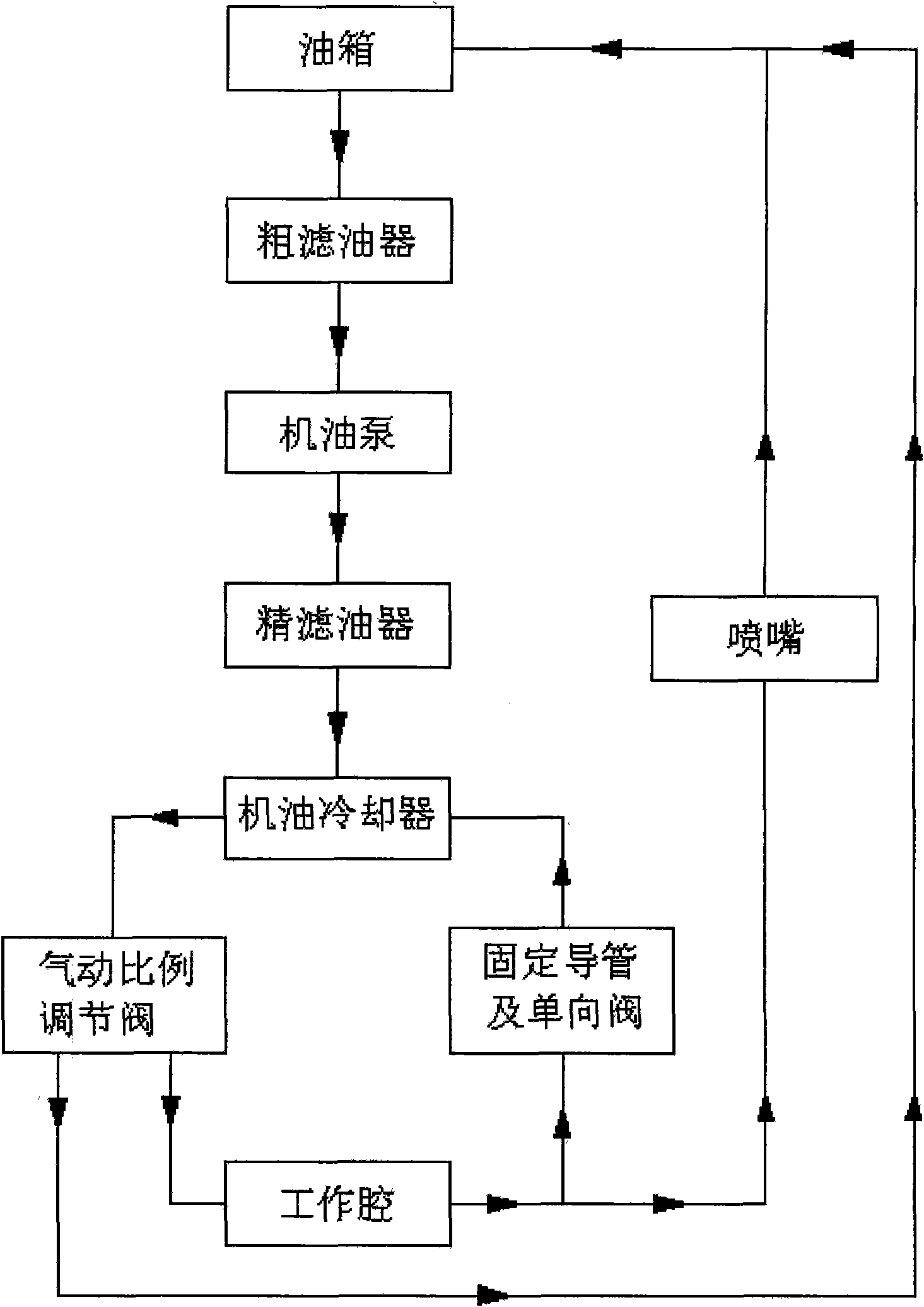
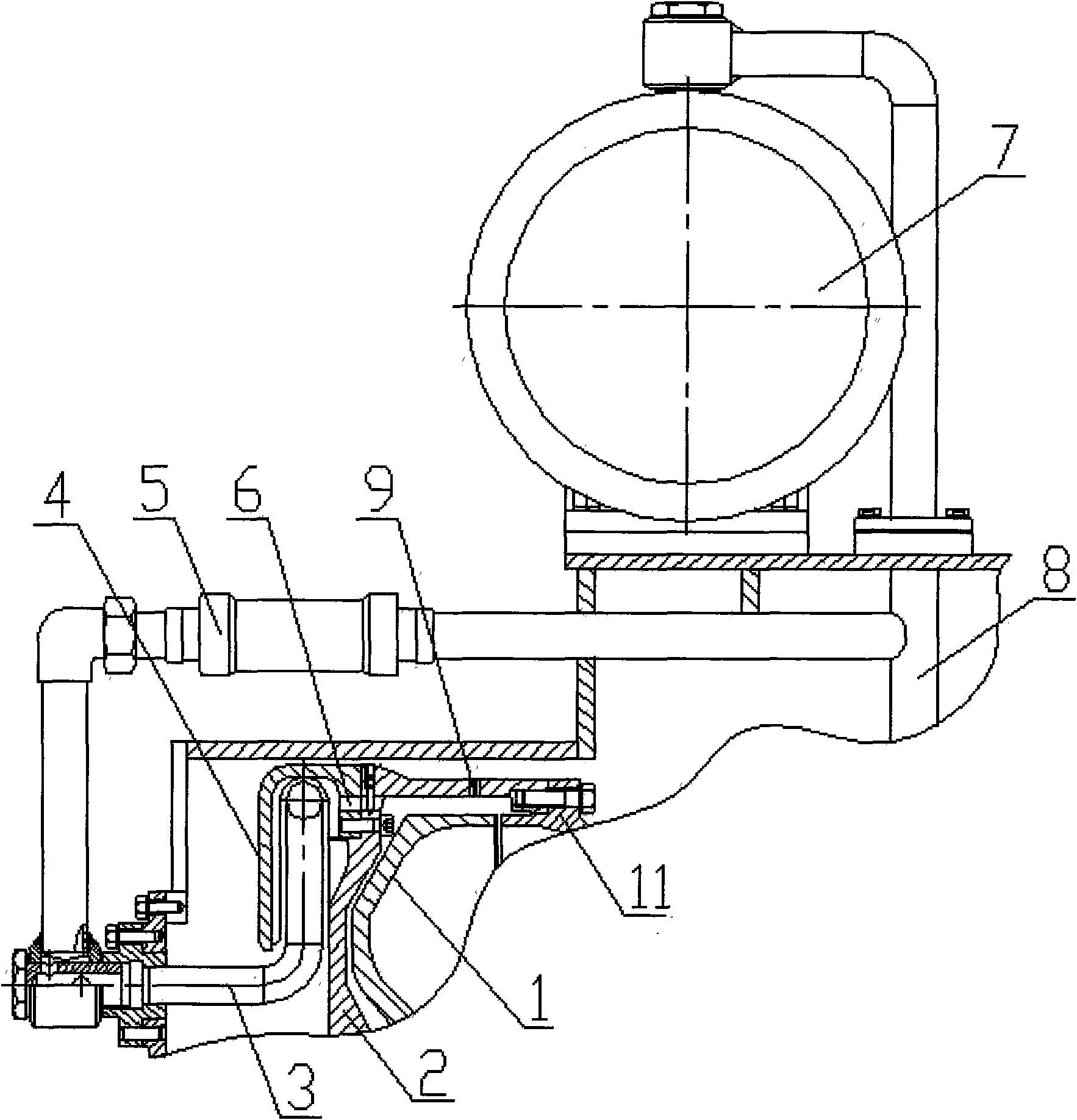
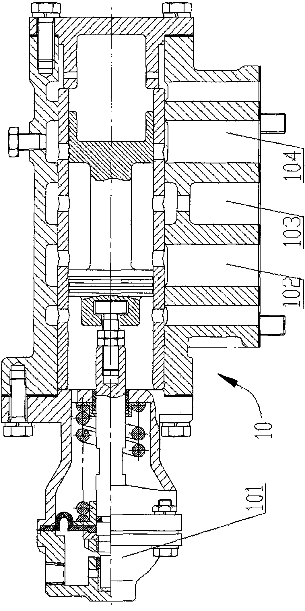
[0012] When the embodiment of the present invention is implemented, its designed main mechanism includes a turbine 1, a pump wheel cover 2, a fixed conduit 3, an outer cover 4, radial blades 41, a one-way valve 5, an oil hole 6, an oil cooler 7, and a main oil circuit 8 , nozzle 9, pneumatic proportional control valve 10 and pump wheel 11. The side wall of the pump wheel cover 2 is provided with a nozzle 9; the outer rigid connection of the pump wheel cover 2 is provided with an outer cover 4, and the inner side of the outer cover 4 is provided with radial blades 41, and the outer cover 4 is provided with a pump wheel 11 and a turbine. The working chamber formed by 1 is connected to the oil hole 6, and the outer cover 4 is provided with a fixed conduit 3, and the opening direction of the fixed conduit 3 faces the direction of the high-speed rotating cycle of the working oil in the outer cover 4, and the fixed conduit 3 is provided with a one-way valve. 5. A pneumatic proportio...


PUM


Abstract

The invention relates to a speed regulating device for a fixed conduit nozzle valve-controlled hydraulic coupler. The speed regulating device comprises an impeller and a turbine, wherein, the side wall of an impeller cover is provided with a nozzle, the outside of the impeller cover is provided with an outer cover, blades are arranged inside the outer cover, the outer cover is provided with oil holes communicated with a working space formed by the impeller and the turbine, and the outer cover is internally provided with a fixed conduit; the opening of the fixed conduit faces high-speed rotating circulation oil enter direction of working oil in the outer cover, the fixed conduit is provided with a check valve, and a pneumatic proportional regulating valve, an electric proportional regulating valve or an electro-pneumatic proportional regulating valve is arranged on an oil circuit at the inlet of the working space. The speed regulating device has the outstanding advantages of being capable of realizing quick 'on / off' functions of the coupler by regulating the proportional regulating valves, and realizing stepless regulation on the filling amount of the working space and the output rotating speed of the coupler.

Description

Technical field: [0001] The invention relates to the technical field of hydraulic couplings, in particular to a fixed conduit nozzle valve-controlled hydraulic coupling speed regulating device. Background technique: [0002] The hydraulic coupling is a non-rigid coupling with liquid as the working medium, also known as the hydraulic coupling. The pump wheel and the turbine of the hydraulic coupling form a closed working chamber that can circulate the liquid. The pump wheel is installed on the input shaft, and the turbine is installed on the output shaft. When the power machine (internal combustion engine, electric motor, etc.) drives the input shaft to rotate, the liquid is thrown out by the centrifugal pump wheel, and the pump wheel converts the mechanical energy of the power machine into the kinetic energy of the working oil. After this high-speed liquid enters the turbine, it drives the turbine to rotate. The turbine converts the kinetic energy of the working oil into me...

Claims


Application Information

Patent Timeline
Patent Type & Authority Applications(China)
IPC IPC(8): F16H41/04F16H41/24
Inventor 赵立华姜小兴张心勤李永强亓俊勇李舜昌杨民俊
Owner BC P INC CHINA NAT PETROLEUM CORP
Learn More