Fluorescent material, scintillator using same, and radiation detector using same
A radiation detector and fluorescent material technology, which is applied in the field of fluorescent materials to achieve the effects of stabilizing detection performance, improving resolution and shortening scanning time
- Summary
- Abstract
- Description
- Claims
- Application Information
AI Technical Summary
Problems solved by technology
Method used
Image
Examples
no. 1 approach
[0100] The fluorescent material of the first embodiment of the present invention is characterized in that Ce is used as a luminescent element, at least Gd, Al, Ga, O and Si are contained, M is at least one of Mg, Ti, and Ni, and is represented by the following general formula :
[0101] (Gd 1-x-z Lu x Ce z ) 3+a (Al 1-u-s Ga u sc s ) 5-a o 12
[0102] in:
[0103] 0≤a≤0.15,
[0104] 0≤x≤0.5,
[0105] 0.0003≤z≤0.0167,
[0106] 0.2≤u≤0.6,
[0107] 0≤s≤0.1,
[0108] The concentrations of Si and M are:
[0109] 0.5≤Si concentration mass ppm≤10,
[0110] 0≤M concentration mass ppm≤50.
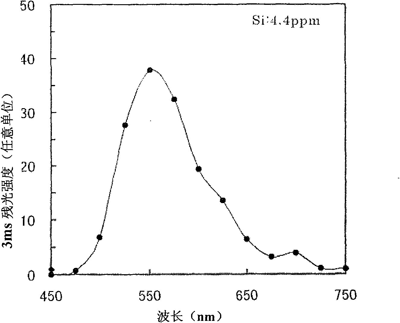
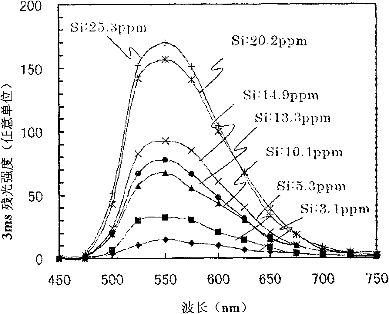
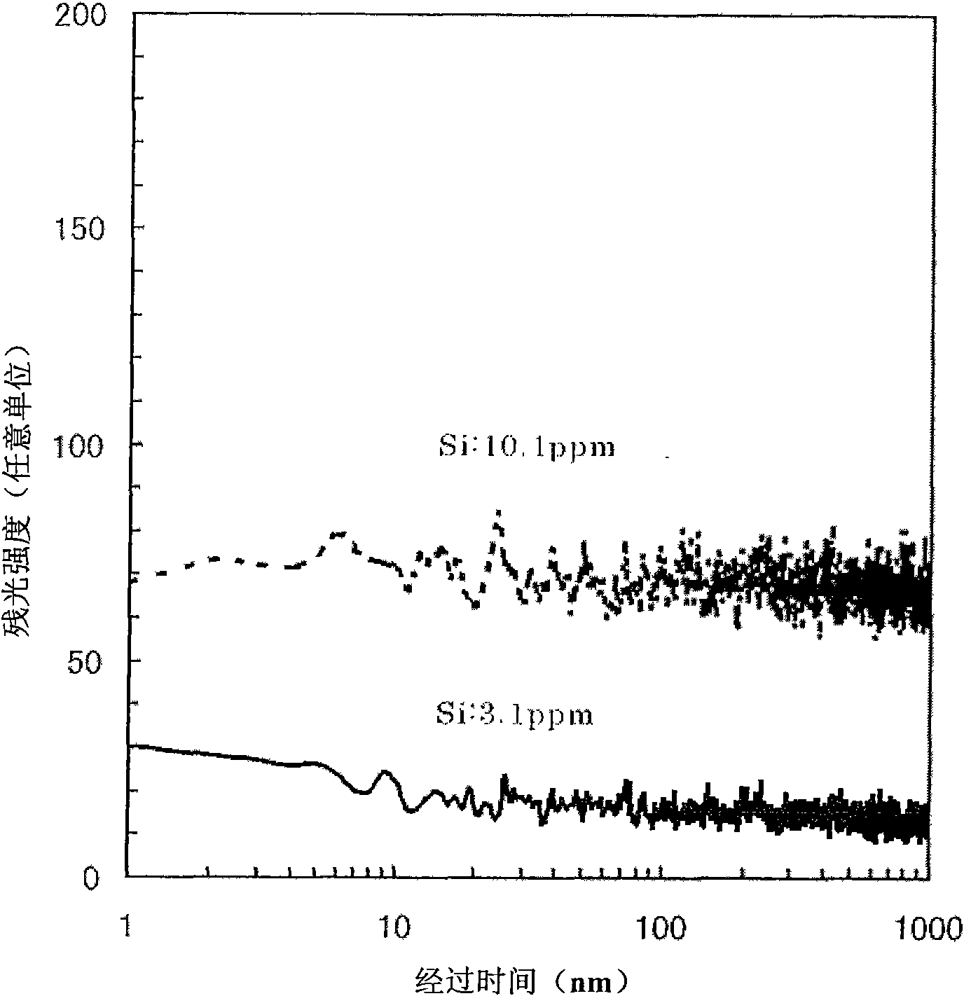
[0111] In the present invention, the material must contain Si. The Si content is 0.5 to 10 mass ppm. according to Figure 4 As a result, when the Si content exceeds 10 mass ppm, the 3ms afterglow exceeds 800 ppm, which is larger than the allowable value, so the upper limit of the Si content is 10 mass ppm (preferably, the upper limit is 5 mass ppm). However, in the raw materials f...
no. 2 approach
[0145] In a second embodiment, the above-mentioned fluorescent material is used as a scintillator, and a radiation detector is provided with the scintillator and a light receiving element for detecting light emitted by the scintillator. The radiation detector is suitable for medical observation devices or inspection devices such as X-ray CT, PET (Positron Emission Tomography) or PET / CT.
[0146] In other words, when the above-mentioned fluorescent material is used as a scintillator, a high-performance radiation detector with high time resolution can be obtained because the luminous intensity is high, the decay time constant is small, and afterglow is small.
[0147] The radiation detector such as Figure 15 , 16 As shown, a structure including a scintillator and a photodetector for detecting the light emission of the fluorescent material can be obtained. Figure 15 It is a perspective view showing a general structure of a radiation detector, Figure 16 yes Figure 15 A-A i...
Embodiment 1
[0152] 200 g of raw materials, 1300 g of high-purity alumina balls with a diameter of 5 mm, and 200 cc of ethanol were placed together in a resin crucible with a capacity of 1 liter. After mixing for 12 hours, the mass of the alumina balls became 0.06 g. Consider Al from the ball 2 o 3 In order to obtain the composition of Example 1 in Table 2, weigh Gd respectively 2 o 3 (Si: 3 mass ppm) 126.91g, CeO 2 0.363g, Al 2 o 3 (Si: 10 mass ppm) 40.62g, Ga 2 o 3 (Si: 10.0 mass ppm) 32.05 g. Gd 2 o 3 A raw material powder having an average particle diameter of 2 μm (here, the average particle diameter is the median particle diameter) was used. al 2 o 3 and Ga 2 o 3 Raw material powders of 0.6 μm and 3 μm were used respectively. al 2 o 3 As the powder, the powder that was subjected to heat treatment at 1400° C. for 1 hour in vacuum (~10 Pa) and then pulverized by a ball mill for 12 hours was used. Through such treatment, Si was reduced from 10 mass ppm to 3 mass ppm. ...
PUM
| Property | Measurement | Unit |
|---|---|---|
| particle diameter | aaaaa | aaaaa |
| particle diameter | aaaaa | aaaaa |
| luminous intensity | aaaaa | aaaaa |
Abstract
Description
Claims
Application Information
 - R&D Engineer
- R&D Manager
- IP Professional
- Industry Leading Data Capabilities
- Powerful AI technology
- Patent DNA Extraction
Browse by: Latest US Patents, China's latest patents, Technical Efficacy Thesaurus, Application Domain, Technology Topic, Popular Technical Reports.
© 2024 PatSnap. All rights reserved.Legal|Privacy policy|Modern Slavery Act Transparency Statement|Sitemap|About US| Contact US: help@patsnap.com


