
High-precision Z-axis carrier platform of picosecond laser process equipment

A processing equipment, picosecond laser technology, used in laser welding equipment, metal processing equipment, welding equipment and other directions, can solve the problem of not meeting the lifting accuracy requirements of picosecond laser fine processing equipment, achieve excellent functions, low manufacturing costs, Design novel effects

Active Publication Date: 2010-02-03
SUZHOU DELPHI LASER
View PDF0 Cites 44 Cited by
  • Summary
  • Abstract
  • Description
  • Claims
  • Application Information

AI Technical Summary

Problems solved by technology

The Z-axis loading platform requires that the platform can be accurately positioned at any time within a certain range of travel, so as to meet the movement and processing requirements of the machine; its repeat positioning accuracy is generally ±3-5um, which is far from meeting the requirements of picosecond laser fine processing equipment. Lifting accuracy requirements

Method used


Image

  • High-precision Z-axis carrier platform of picosecond laser process equipment
  • High-precision Z-axis carrier platform of picosecond laser process equipment
  • High-precision Z-axis carrier platform of picosecond laser process equipment

Examples


Embodiment Construction

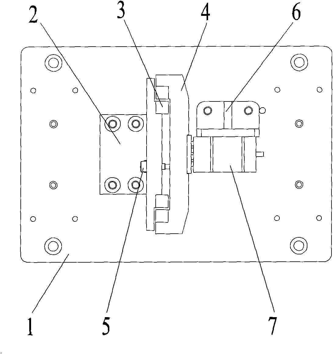
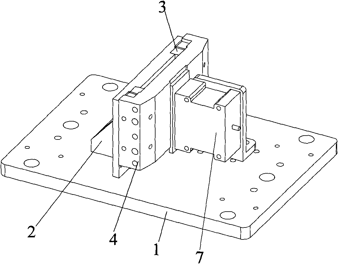
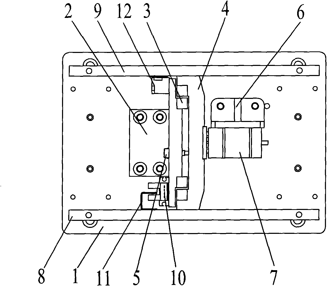
[0024] High-precision Z-axis loading platform for picosecond laser processing equipment, such as Figure 1a , Figure 1b , the Z platform bottom plate 1 is the basic component, the Z fixed plate 2 is fixed on the Z platform bottom plate 1, the Z fixed plate 2 has an L-shaped structure, including a horizontal plane and a vertical plane, and the horizontal plane of the Z fixed plate 2 is fixed to the Z platform bottom plate 1 Connect, install vertical guide rail 3 on the vertical surface of Z fixed plate 2, install a lifting plate 4 that can move up and down along guide rail 3 on the guide rail 3, be used to control the piezoelectric ceramic motor 7 that lift plate 4 moves up and down through motor installation The plate 6 is fixed on the bottom plate 1 of the Z platform. The motor mounting plate 6 has an L-shaped structure, including a horizontal plane and a vertical plane. The piezoelectric ceramic motor 7 has a ceramic sheet attached to the lifting plate 4. When the piezoelec...


PUM


Abstract

The invention relates to a high-precision Z-shaft carrier platform of picosecond laser process equipment. A Z fixed plate is fixed on the base plate of a Z platform, a vertical guide rail is installedon the Z fixed plate, an elevating plate capable of moving upwards and downwards along the guide rail is installed on the guide rail, a piezoelectric ceramic motor for controlling the elevating plateto move upwards and downwards is installed on the base plate of the Z platform, a vertical front side plate is fixed on the front side surface of the elevating plate, a vertical back side plate is fixed on the back side surface of the elevating plate, and the front side plate and the back side plate are arranged symmetrically in parallel; a sensor is arranged on the Z fixed plate, and the internal surface of the front side plate or the back side plate is provided with a sensing plate of the sensor; a reading head is arranged on the Z fixed plate, and a grating gage is stuck to the internal surface of the front side plate or the back side plate; and fixture plates are arranged on the front side plate and the back side plate. The high-precision Z-shaft carrier platform of the picosecond laser process equipment controls the Z-shaft to start, stop and elevate by using the high-resolution piezoelectric ceramic motor. The grating gage ensures the precision of elevation and positioning. Thebalancing mechanism solves the problems of insufficient thrust and static retaining force of the piezoelectric ceramic motor.

Description

technical field [0001] The invention relates to picosecond laser finishing equipment, in particular to a high-precision Z-axis object-carrying platform of the picosecond laser processing equipment. Background technique [0002] At present, in laser fine processing equipment, the Z-axis loading platform is generally driven by the motor rotation to move the ball screw to perform linear motion, and then the linear motion of the ball screw drives the loading platform to realize vertical lifting. The Z-axis loading platform requires that the platform can be accurately positioned at any time within a certain range of travel, so as to meet the movement and processing requirements of the machine; its repeat positioning accuracy is generally ±3-5um, which is far from meeting the requirements of picosecond laser fine processing equipment. Lifting accuracy requirements. Contents of the invention [0003] The purpose of the present invention is to overcome the deficiencies in the pri...

Claims


Application Information

Patent Timeline
IPC IPC(8): B23K26/42B23K26/70
Inventor 赵裕兴徐礼江
Owner SUZHOU DELPHI LASER
Learn More