Method of and apparatus for controlling excitation

A technology of exciter and excitation control, which is applied in the direction of control system, control of generator, control of generator through magnetic field change, etc. It can solve the problems of reducing the rating of the generator, affecting the active material and cost, etc.

Active Publication Date: 2010-01-20
CUMMINS GENERATOR TECH LTD
View PDF0 Cites 4 Cited by
  • Summary
  • Abstract
  • Description
  • Claims
  • Application Information

AI Technical Summary

Problems solved by technology

Also, generator de-rating is required, again impacting active material and cost

Method used


Image

  • Method of and apparatus for controlling excitation
  • Method of and apparatus for controlling excitation
  • Method of and apparatus for controlling excitation

Examples


Embodiment Construction

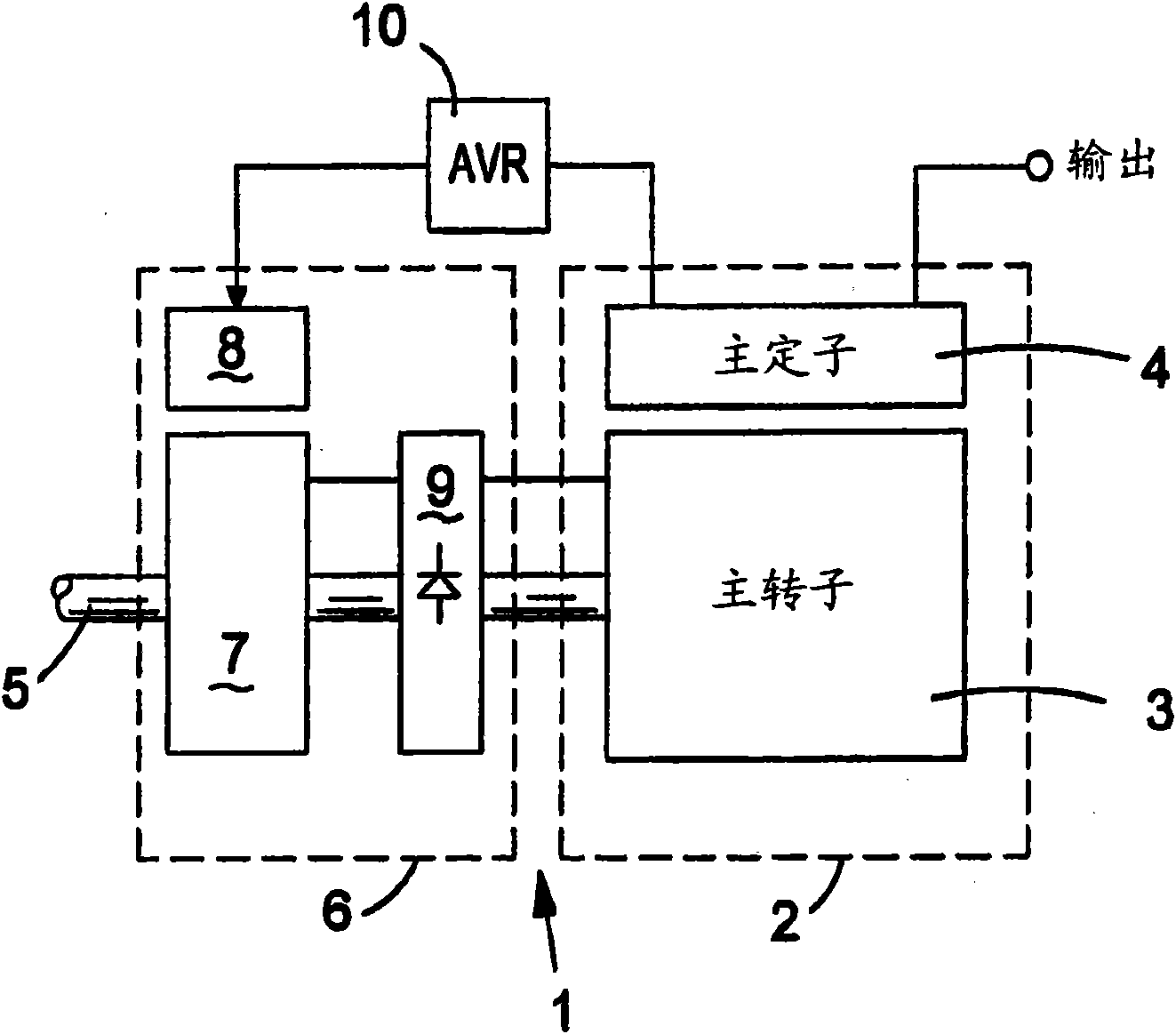
[0038] figure 1 The components of the synchronous generator 1 are shown. The generator includes a main engine 2 which includes a main rotor 3 and a main stator 4. The main rotor 3 is located on a shaft 5, which is driven by a prime mover such as a diesel engine (not shown). The main rotor generates a magnetic field so that rotation of the main rotor relative to the main stator causes AC output in the main stator windings.

[0039] The main rotor is magnetized by passing a DC current through the rotor winding. This DC current is generated by an exciter 6 which includes an exciter rotor 7, an exciter stator 8 and a rotating diode 9. The exciter rotor 7 is mounted on the shaft 5, and the rotation of the exciter rotor 7 relative to the exciter stator 8 produces an AC output in the exciter rotor winding. This AC output is converted into DC by the rotating diode 9 and the DC output of the rotating diode is fed to the main rotor 3.

[0040] in figure 1 In the arrangement, the power fo...


PUM


Abstract

Excitation control circuitry for a synchronous generator is disclosed. The synchronous generator is of a type comprising a main machine (2) and an exciter (6) for exciting the main machine. The excitation control circuitry comprises an automatic voltage regulator (10) for controlling power flow from the main machine to the exciter, and an excitation boost system (14) for selectively supplying power from a second source of electrical power (12) to the exciter (6). This can allow additional excitation to be provided, for example, when the generator is in overload. This arrangement can allow a synchronous generator to be upgraded by adding the excitation boost system to provide enhanced overload performance.

Description

Technical field [0001] The invention relates to a method and device for controlling excitation in a synchronous generator. Background technique [0002] Synchronous generators work by rotating the magnetic field generated by the rotor with respect to the windings in the stator to generate AC output in the stator windings. By passing DC current through the windings in the rotor, the magnetic field of the rotor can be generated. This DC current can be generated by an exciter mounted on the shaft of the generator. An automatic voltage regulator (AVR) can be provided to control the exciter, thereby controlling the current supplied to the rotor winding. [0003] A synchronous generator generally has a maximum rated load, which is the maximum load that the generator can supply under steady-state conditions. In addition, certain applications may require generators with short-circuit maintenance and / or enhanced overload capabilities. Applications that require this include (among other ...

Claims


Application Information

Patent Timeline
Patent Type & Authority Applications(China)
IPC IPC(8): H02P9/10H02P9/38
CPCH02P9/10H02P9/38H02P9/107
Inventor N·杰克曼M·J·赖特D·H·达尔比N·布朗
Owner CUMMINS GENERATOR TECH LTD
Why Eureka
Try Eureka