Method for detecting synchronous vibration parameters of high-speed rotary blade under constant speed
A technology of synchronous vibration and high-speed rotation, which is applied in the direction of vibration measurement in solids, measuring vibration, measuring devices, etc., to simplify the measurement process and meet the effect of real-time online monitoring
Active Publication Date: 2011-01-05
ZHEJIANG ZHONGXIN POWER MEASUREMENT & CONTROL TECH
View PDF0 Cites 2 Cited by
- Summary
- Abstract
- Description
- Claims
- Application Information
AI Technical Summary
Problems solved by technology
The above synchronous vibration detection methods need to operate at a uniform speed of the rotating machinery as a prerequisite, which has certain limitations.
Method used
View moreImage
Smart ImageViewing Examples
Examples
Embodiment Construction
Login to View More PUM
 Abstract
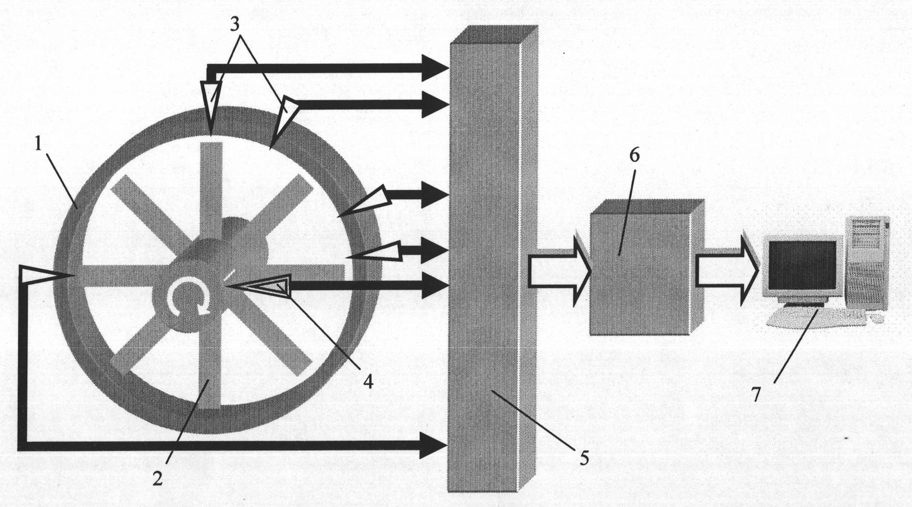
The invention relates to a method for detecting vibration of a blade of a rotary machine, in particular to a method for detecting synchronous vibration parameters of a high-speed rotary blade under a constant speed. In order to eliminate limitation of taking uniform variable speed running as a precondition and meet the demand of real-time online monitoring, the invention adopts the technical scheme that based on a bladetip timing vibration detection principle, the synchronous vibration displacement yi of a certain blade, detected by a bladetip timing sensor, is indicated as following: yi=Asin(Nealphai+Phi0)+C(i=0,1,2...). A frequency doubling traversal range containing actual synchronous vibration frequency doubling Ne of the blade is selected, and then an actual installing included anglealphai of the bladetip timing sensor and the selected frequency doubling Nej are substituted into the formula so as to work out the vibration displacement of different frequency doubling corresponding to a multiple-sensor theory measured by a least square method; the square and the radix of an error between the calculated vibration displacement and the vibration displacement of actual measurementare worked out, and the frequency doubling of the minimum value of the square and the radix of the error is taken as the frequency doubling value of the actual vibration of the blade in a frequency doubling traversal process. The invention is mainly applied to the method for detecting the vibration of the blade of the rotary machine.
Description
Detecting Method of Synchronous Vibration Parameters of High Speed Rotating Blades at Constant Speed technical field The present invention relates to a method for detecting the vibration of rotating mechanical blades, more specifically, the present invention relates to a method for detecting synchronous vibration parameters of high-speed rotating blades with random distribution of multi-sensors under the condition of constant speed based on the blade tip timing principle. Background technique Blade tip timing vibration measurement technology plays an important role in the field of real-time monitoring and fault diagnosis of rotating machinery. Higher requirements are put forward, which prompts it to develop in the direction of high-precision and comprehensive parameter detection. The blade tip timing vibration measurement technology is a non-contact detection method. Its basic principle is to install the blade tip timing sensor on the relatively stationary shell of the r...
Claims
Login to View More Application Information
Patent Timeline
 Patent Type & Authority Patents(China)
IPC IPC(8): G01H13/00G01H1/00
Inventor 段发阶李孟麟欧阳涛孔祥洪
Owner ZHEJIANG ZHONGXIN POWER MEASUREMENT & CONTROL TECH
Features
- Generate Ideas
- Intellectual Property
- Life Sciences
- Materials
- Tech Scout
- Unparalleled Data Quality
- Higher Quality Content
- 60% Fewer Hallucinations
Learn More Browse by: Latest US Patents, China's latest patents, Technical Efficacy Thesaurus, Application Domain, Technology Topic, Popular Technical Reports.
© 2025 PatSnap. All rights reserved.Legal|Privacy policy|Modern Slavery Act Transparency Statement|Sitemap|About US| Contact US: help@patsnap.com


