
Small-size multi-way valve operating mechanism assembly

A control mechanism, multi-way valve technology, applied in the direction of valve operation/release device, valve detail, valve device, etc., can solve the problems of large volume, large space, and inability to control the direction or position of the vehicle.

Inactive Publication Date: 2010-01-20
LUOYANG YELLOW RIVER FLEXIBLE SHAFT CONTROLLER
View PDF0 Cites 6 Cited by
  • Summary
  • Abstract
  • Description
  • Claims
  • Application Information

AI Technical Summary

Problems solved by technology

[0002] Known multi-way valves are used in a wide range of fields. They are mainly used to control the flow direction of hydraulic oil. In use, there are single-lever control to achieve a single function, and there are also those that require two-way valves to achieve compound actions; such as skid steer loaders. Bucket boom control requires that when the boom is lifted or lowered while the bucket has to flip, etc., it is realized through the multi-way valve control mechanism to issue instructions; if it is two-lever control, the driver requires both hands Control, because it is controlled by both hands, it is impossible to control the direction or position of the vehicle
Moreover, most of the existing single-rod dual-axis multi-way valves use universal cross shafts for direction conversion. The disadvantage of this structure is that it is too bulky and has no mid-position anti-misoperation locking function; It takes up too much space when used on the road, and at the same time requires the driver to lock the hydraulic control device after leaving the vehicle to prevent accidents

Method used


Image

  • Small-size multi-way valve operating mechanism assembly
  • Small-size multi-way valve operating mechanism assembly
  • Small-size multi-way valve operating mechanism assembly

Examples


Embodiment Construction

[0014] The present invention can be explained in more detail with reference to the following examples; however, it should be noted that the present invention is not limited to the following examples.

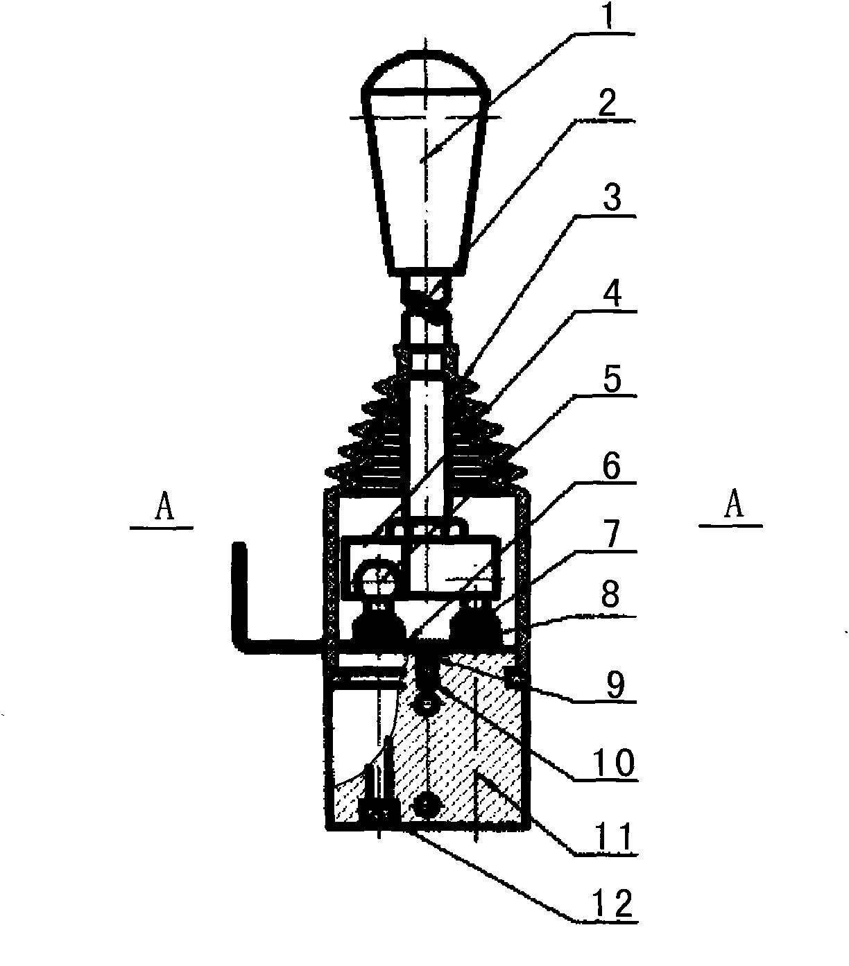
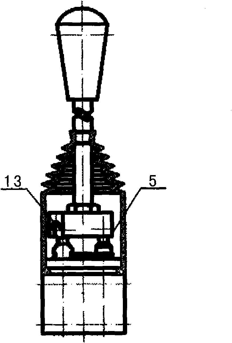
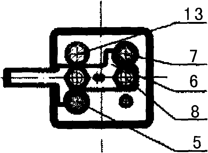
[0015] exist figure 1 , 2 , The small multi-way valve control mechanism assembly described in 3, the control handle 1 is arranged on the upper end of the handle bar 2, and a dust-proof rubber sheath 3 is set on the lower part of the handle bar 2, and the lower part of the dust-proof rubber sheath 3 is a The side of the side is provided with a through hole, and the lower end of the dustproof rubber sheath 3 is stuck on the upper part of the controller base 11. The dustproof rubber sheath 3 is a cavity structure, and it is characterized in that: the lower end of the handle rod 2 is in the dustproof rubber sheath. The cover 3 is connected to the upper surface of the handle rocker seat 4, and the lower part of the handle rocker seat 4 is provided with two hole-type chute correspond...


PUM


Abstract

The invention discloses a small-size multi-way valve operating mechanism assembly, relating to the technical field of mechanical transmission control; a maneuvering handle (1) is arranged at the upper end of a handle bar (2); a dust-proof rubber sheath (3) is sheathed at the lower part of the handle bar; the lower end of the dust-proof rubber sheath is sheathed and clamped at the upper part of a controller base (11); the lower end of the handle bar is connected with the upper face of a handle rock shaft (4) in the dust-proof rubber sheath; the upper ends of a sliding connecting rod A (5), a sliding connecting rod B (7) and a supporting connecting rod (13) are respectively a spherical structure; and the sliding connecting rod A, the sliding connecting rod B and the supporting connecting rod are respectively matched with two hole-shaped sliding chutes of the handle rock shaft in a sliding manner. The invention has flexible manipulation and single-rod dual-axis control function, can realize independent movement of each sliding rod according to actual requirements and can realize homodromous or reversed motion of the two sliding rods, thereby preventing accidents from occurring.

Description

【Technical field】 [0001] The invention relates to the technical field of mechanical transmission control, in particular to a small multi-way valve control mechanism assembly. 【Background technique】 [0002] Known multi-way valves are used in a wide range of fields. They are mainly used to control the flow direction of hydraulic oil. In use, there are single-lever control to achieve a single function, and there are also those that require two-way valves to achieve compound actions; such as skid steer loaders. Bucket boom control requires that when the boom is lifted or lowered while the bucket has to flip, etc., it is realized through the multi-way valve control mechanism to issue instructions; if it is two-lever control, the driver requires both hands Control, because it is controlled by both hands, it is impossible to control the direction or position of the vehicle. Moreover, most of the existing single-rod dual-axis multi-way valves use universal cross shafts for directi...

Claims


Application Information

Patent Timeline
IPC IPC(8): F16K31/60F16K41/10F15B13/02
Inventor 杨长儒郭兰草庞媛媛杜万庆杨钧杜庆丽周喜
Owner LUOYANG YELLOW RIVER FLEXIBLE SHAFT CONTROLLER
Learn More