Backlight module and diffusion plate thereof

A technology of backlight module and diffusion plate, which is applied in optics, optical components, nonlinear optics, etc., and can solve the problems of reducing light utilization rate, increasing light transmission interface loss, light loss, etc.

Inactive Publication Date: 2010-01-13
HONG FU JIN PRECISION IND (SHENZHEN) CO LTD +1
View PDF0 Cites 5 Cited by
  • Summary
  • Abstract
  • Description
  • Claims
  • Application Information

AI Technical Summary

Problems solved by technology

[0005] However, when the light is transmitted in the prism sheet 10 and the upper diffusion sheet 14, part of the light will be absorbed and cause light loss; The number of interfaces increases the interface loss of light transmission and reduces light utilization

Method used


Image

  • Backlight module and diffusion plate thereof
  • Backlight module and diffusion plate thereof
  • Backlight module and diffusion plate thereof

Examples


Embodiment Construction

[0018] Hereinafter, the backlight module and the diffusion plate of the present invention will be further described in detail with reference to the accompanying drawings and embodiments.

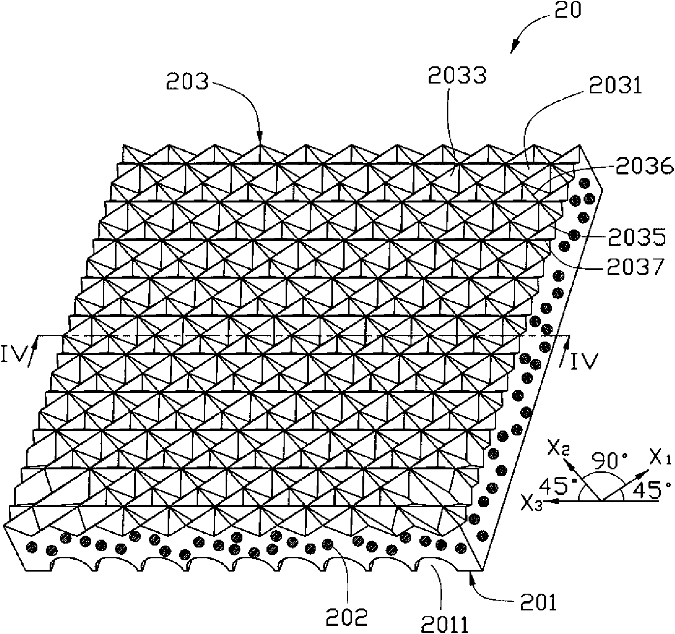
[0019] See image 3 and Figure 4 , The diffuser 20 of the preferred embodiment 1 of the present invention is shown, which includes a body having a first surface 201 and a second surface 203 opposite to the first surface 201.

[0020] The body is made of a transparent material in which scattering particles 202 are dispersed. The transparent material is one or a mixture of polymethyl methacrylate, polycarbonate, polystyrene, and styrene-methyl methacrylate copolymer. The body also includes scattering particles 202 dispersed in the transparent material. The scattering particles 202 are one or a combination of titanium dioxide particles, silicon dioxide particles and acrylic resin particles, which can scatter and diffuse light irradiated thereon. It can be understood that by adjusting the composit...


PUM

PropertyMeasurementUnit
angleaaaaaaaaaa
depthaaaaaaaaaa

Abstract

A backlight module comprises a frame, a light source and a diffusion plate; wherein, the light source is positioned in the frame; the diffusion plate is positioned above the light source and comprises a body; the body is made of transparent materials in which scattering particles are dispersed and comprises a first surface and a second surface opposite to the first surface; the first surface is provided with a plurality of mutually parallel long strip arc grooves; the second surface is provided with a plurality of triangular pyramid shaped grooves and rectangular pyramid shaped grooves; each rectangular pyramid shaped groove is enclosed by four adjacent triangular pyramid shaped grooves. The invention also provides the diffusion plate adopted by the backlight module. The backlight module has the advantages of improving effective utilization ratio of light and enjoying uniformity of light emission.

Description

Technical field [0001] The invention relates to a backlight module and its diffusion plate, in particular to a backlight module and its diffusion plate for liquid crystal display. Background technique [0002] See figure 1 , Shown is an existing direct type backlight module 100, which includes a frame 11, a plurality of light sources 12 arranged inside the frame 11, and a diffuser 13 arranged above the light source 12. [0003] In use, the light generated by multiple light sources 12 can be diffused after entering the diffuser 13. However, after being diffused by the diffuser 13, the exit angle of the light from the diffuser 13 becomes more messy, making its brightness in a specific viewing angle range low; and because the light source 12 transmits more light directly above it, it diffuses It is often difficult for the plate 13 to directly diffuse the light from the light source 12 uniformly, so that the light emitted from the diffusion plate 13 is prone to light source afterimage...

Claims


Application Information

Patent Timeline
Patent Type & Authority Applications(China)
IPC IPC(8): G02F1/13357G02B5/02G02B1/04
Inventor 章绍汉
Owner HONG FU JIN PRECISION IND (SHENZHEN) CO LTD
Why Eureka
Try Eureka