Vent stop valve of pressure gauge

A technology for pressure gauges and globe valves, which is applied in the direction of measuring fluid pressure, valve details, valve devices, etc. It can solve problems such as unsafety, pressure relief, and increased danger to operators, so as to ensure sealing accuracy, prolong service life, The effect of high safety performance

Inactive Publication Date: 2010-01-13
严俭祥
View PDF0 Cites 4 Cited by
  • Summary
  • Abstract
  • Description
  • Claims
  • Application Information

AI Technical Summary

Problems solved by technology

[0002] Pressure gauge globe valves are widely used in industrial production processes such as chemical industry, petroleum, metallurgy, mining, electric power, energy, and environmental protection. They are used to connect pressure gauges, measure and manage pressure, and discharge dirt to pipelines for conveying media as needed. , or timely sampling for component analysis, the pressure gauge cut-off valve in the current technology can only be used to install pressure instruments, because it is impossible to discharge the pipeline sewage and pressure in time, especially when the valve is closed, it is impossible to empty the valve body and The medium pressure in the pressure gauge brings unsafe production, especially the long-term high pressure in the valve body and pressure gauge, which greatly affects the accuracy, sealing, service life and safety performance of the pressure gauge and valve, and , in actual use, when the operator repairs, inspects or replaces the pressure gauge, because the pressure gauge is in a high pressure state, the medium pressure in the gauge cannot be released in time, which increases the danger of the operator

Method used


Image

  • Vent stop valve of pressure gauge
  • Vent stop valve of pressure gauge
  • Vent stop valve of pressure gauge

Examples


Embodiment Construction

[0014] The specific implementation manner of the present invention will be further described below in conjunction with the accompanying drawings.

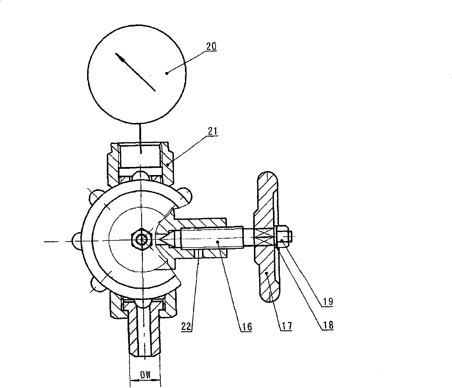
[0015] like figure 1 , figure 2 , image 3 As shown, a pressure gauge venting stop valve of the present invention includes a connecting pipe 1, a gasket 2, a connecting nut 3, a valve body 4, a packing pad 5, a lower valve stem 6, a packing 7, a pressure ring 8, a half ring 9, a lock Tight nut 10, stem nut 11, upper stem 12, handwheel 13, washer 14, nut 15, vent stem 16, vent handwheel 17, vent washer 18, vent nut 19, pressure gauge 20, pressure gauge nut 21 , Venting hole 22, wherein the connecting pipe 1 is put into the gasket 2, the connecting nut 3 is put into the connecting pipe 1, and then the valve body 4 is screwed on, and the packing pad 5, packing 7, and packing pressure ring 8 are sequentially put into the inner cavity of the valve body 4, and the lower The valve stem 6 and the upper valve stem 12 are put into the ca...


PUM


Abstract

The invention relates to a vent stop valve of a pressure gauge. The vent stop valve comprises a connecting pipe, a gasket, a connecting pipe nut, a valve body, a packing pad, a lower valve rod, filler, a compression ring, a blocking semi-ring, a locking nut, a valve rod nut, an upper valve rod, a hand wheel, a washer, a nut, a vent valve rod, a vent hand wheel, a vent washer, a vent nut, the pressure gauge, a pressure gauge nut and a vent hole. The vent stop valve is characterized in that the front of the valve body is additionally provided with a vent operating device, wherein the vent valve rod is connected with the valve body; the vent hand wheel is filled in the vent valve rod; the vent washer and the vent nut are connected with the vent hand wheel; the vent hole is at the lower part of the vent valve rod, a vent passage in the vent hole is connected with a valve chest; the vent hand wheel is screwed tightly clockwise; the vent passage in the vent hole is closed; when the valve is closed, the vent valve rod is turned counterclockwise, and the high pressure media in the pressure gauge and the valve chest is depressurized and vented through the vent hole; when a pipeline system requires depressurization, venting and pollution discharge, the valve is opened, the vent valve rod is turned counterclockwise and instantly the vent hole is ready for depressurization or pollution discharge.

Description

technical field [0001] The invention relates to a valve for installing a pressure gauge in a gas medium pipeline under high temperature and high pressure, measuring and managing pressure and releasing pressure, in particular to a pressure gauge venting stop valve. Background technique [0002] Pressure gauge globe valves are widely used in industrial production processes such as chemical industry, petroleum, metallurgy, mining, electric power, energy, and environmental protection. They are used to connect pressure gauges, measure and manage pressure, and discharge dirt to pipelines for conveying media as needed. , or timely sampling for component analysis, the pressure gauge cut-off valve in the current technology can only be used to install pressure instruments, because it is impossible to discharge the sewage and pressure in the pipeline in time, especially when the valve is closed, it is impossible to empty the valve body and The medium pressure in the pressure gauge brin...

Claims


Application Information

Patent Timeline
Patent Type & Authority Applications(China)
IPC IPC(8): G01L19/06F16K31/60F16K41/02F16K37/00
Inventor 严俭祥
Owner 严俭祥
Why Eureka
Try Eureka