Gate line driving device of liquid crystal display

A liquid crystal display and driving device technology, applied in static indicators, instruments, nonlinear optics, etc., can solve the problems of reducing device stability, amorphous silicon film degradation, performance degradation, etc., to improve reliability and reduce bias voltage the effect of time

Inactive Publication Date: 2010-01-06
NANJING CEC PANDA LCD TECH
View PDF0 Cites 10 Cited by
  • Summary
  • Abstract
  • Description
  • Claims
  • Application Information

AI Technical Summary

Problems solved by technology

If the gate of the amorphous silicon thin film transistor is subjected to DC bias for a long time, it will cause the deterioration of the amorphous silicon thin film and many defects will appear, which will cause the threshold voltage (threshold voltage) of the amorphous silicon thin film transistor to become very large
Thus, in figure 2 With the circuit structure shown, after working for a period of time, the performance of the pull-down TFT will deteriorate, and the critical voltage will drift upwards, so that the voltage of the output signal cannot be fully charged, so the gate driver device with this structure cannot work normally for a long time. Work
[0006] The above structure cannot prevent the gate of the pull-down TFT from being under high DC bias voltage for a long time, which will cause the film quality of the amorphous silicon thin film transistor to deteriorate and cause the drift of the threshold voltage, thereby affecting the output characteristics of the shift register and reducing the stability of the device.

Method used


Image

  • Gate line driving device of liquid crystal display
  • Gate line driving device of liquid crystal display
  • Gate line driving device of liquid crystal display

Examples


Embodiment Construction

[0015] The present invention will be further described below with reference to the accompanying drawings and typical embodiments.

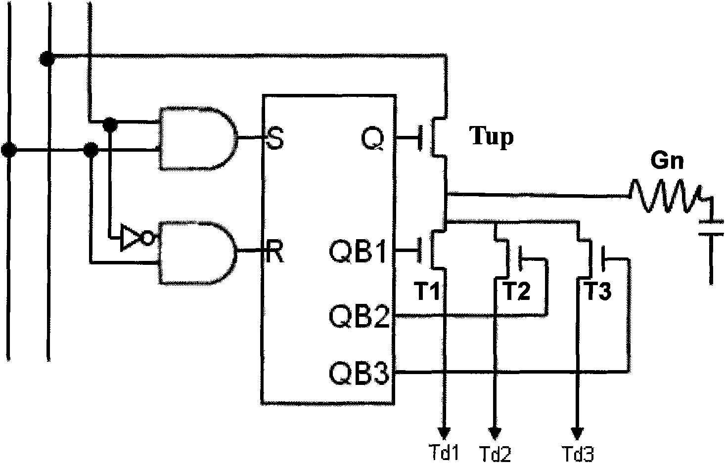
[0016] image 3 It is a schematic structural diagram of the gate driver device of the present invention.

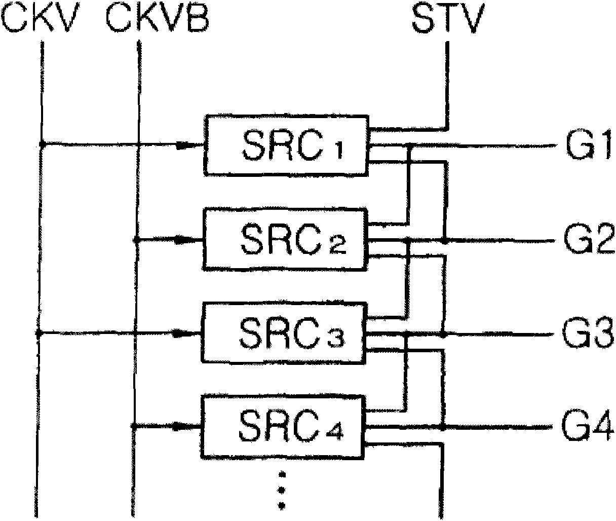
[0017] See figure 1 and image 3 , the gate line drive device provided by the present invention includes a plurality of gate line drive units (SRC1, SRC2, SRC3, ...), each gate line drive unit includes a shift register, a pull-up circuit and a pull-down circuit, The shift register provides a pull-up drive signal and a pull-down drive signal for the pull-up circuit and the pull-down circuit; each drive unit provides a clock input terminal, a set terminal and an output terminal. The clock input terminals are respectively connected with the clock signal CKV and the clock signal CKVB, and the clock signal CKV and the clock signal CKVB have opposite phases; the plurality of gate line driving units are connected in series in sequence. For examp...


PUM


Abstract

The invention relates to a gate line driving device of a liquid crystal display, comprising a plurality of gate line driving units, wherein each gate line driving unit comprises a shifting register, a pull-up circuit and a pull-down circuit, the gate line driving units are sequentially connected in series, and an output terminal of each gate line driving unit is connected with a current gate line, wherein the pull-down circuit comprises n pull-down control switches; and the shifting register sequentially provides periodic pull-down driving signals by dividing time for the n pull-down control switches, wherein n is a positive integer and is greater than and equal to 3. The gate line driving device of the liquid crystal display greatly reduces the voltage bias time of an amorphous silicon film transistor through the time division work of a plurality of pull-down circuits, thereby enhancing the reliability of the amorphous silicon film transistor.

Description

technical field [0001] The invention relates to a gate line driving device of a liquid crystal display, in particular to a gate line driving device of a liquid crystal display with improved gate line driving capability. Background technique [0002] Liquid crystal display devices (LCDs) have been widely used in terminal display devices of various sizes, due to their light weight, small size and thin thickness. The LCD includes an LCD panel for displaying images and data and gate driving circuits for driving the LCD panel. The LCD panel includes a plurality of gate lines, data lines, and a plurality of pixels. Each pixel includes a thin film transistor (TFT) and a liquid crystal capacitor. The data driving circuit outputs the data signal to the data line, and the gate driving circuit outputs the gate driving signal to the gate line. [0003] In order to reduce the cost, the gate drive circuit can be made on the panel. Currently, amorphous silicon has been used to fabricat...

Claims


Application Information

Patent Timeline
Patent Type & Authority Applications(China)
IPC IPC(8): G09G3/36G02F1/1362
Inventor 周思思黄秋平
Owner NANJING CEC PANDA LCD TECH
Why Eureka
Try Eureka