
Novel wind power station

A power station, a new type of technology, applied in wind power generation, wind power motor combination, wind power generator components, etc., can solve the problems of high cost, difficult wind wheel, difficult transportation and installation, etc., and achieve reduced maintenance cost, ingenious assembly and cost reduction Effect

Inactive Publication Date: 2009-12-30
刘新广
View PDF0 Cites 1 Cited by
  • Summary
  • Abstract
  • Description
  • Claims
  • Application Information

AI Technical Summary

Problems solved by technology

However, due to the long blades of the wind rotor (one or two meters short and more than ten meters long), the generators driven by the wind rotors are heavy, and the towers for installing the wind rotors and generators must be tall. , The tower is difficult, the transportation and installation are difficult, and heavy equipment and heavy vehicles are necessary
Therefore, the existing technology to build a wind power station is expensive and difficult to maintain

Method used


Image

  • Novel wind power station
  • Novel wind power station
  • Novel wind power station

Examples


Embodiment 1

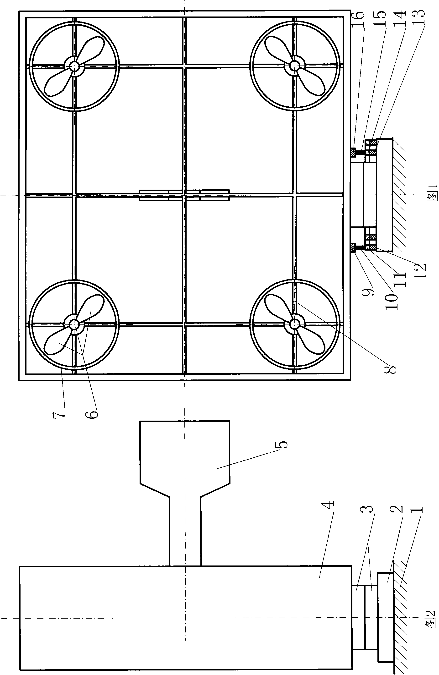
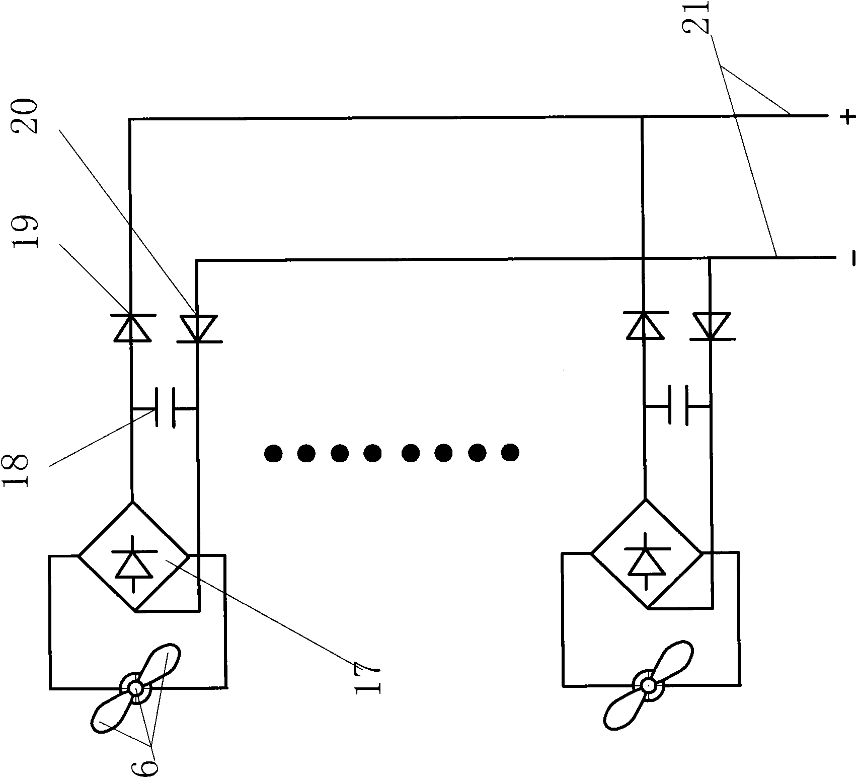
[0021] Embodiment one: if figure 1 figure 2 As shown, several small wind generators 6 are arranged and installed in a rectangular or circular frame 4. The wind generators 6 are composed of wind impellers and generators. The wind generators 6 are supported in the ring 7 by connecting rods 8, and each ring The outer circle of 7 is connected, and the outer circle of each annulus 7 near the inner wall of rectangle or circular frame 4 directly or connects with the inner wall of rectangular or circular frame 4 with connecting rod 8; A wind vane 5 is installed in the center of a vertical section, the bottom of the rectangular or circular frame 4 is connected to the base 2 with a thrust bearing 3, and the bottom of the rectangular or circular frame 4 is also fixed with insulating blocks 9 and 16, which are respectively connected on the insulating blocks 9 and 16 Carbon brush assemblies 10 and 15, the base 2 is set on the foundation 1; insulating rings 12 and 13 are arranged on the f...

Embodiment 2

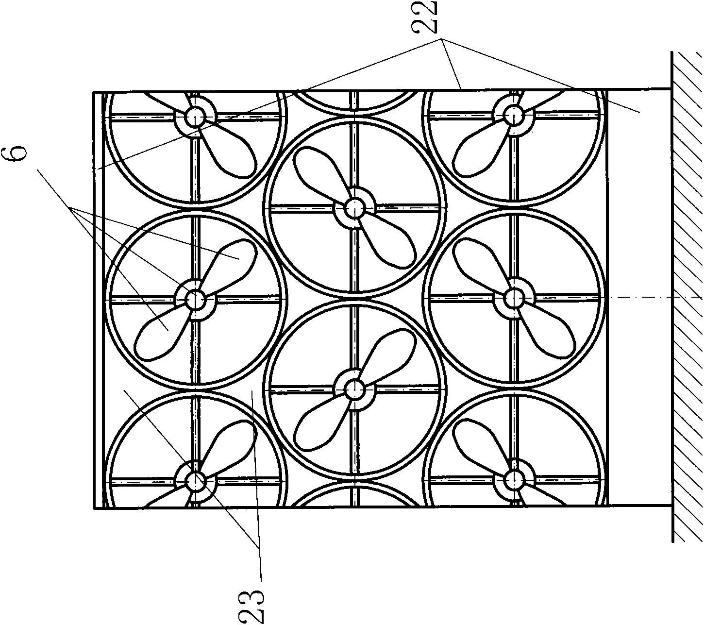
[0022] Embodiment two: if Figure 4 Figure 5 Show. Several small wind-driven generators 6 are arranged and installed in the vertical cylindrical frame 22, and the wind-driven generators 6 are supported in the rings 7 with connecting rods 8, and the outer circles of the rings 7 are connected to each other. The excircle of each annulus 7 of upper top or lower end directly or links with cylindrical frame 22 with connecting rod 8; The bottom of cylindrical frame 22 is fixed on the foundation. The power transmission method is basically the same as Scheme 1, but the generated electricity is directly output from the terminal of the bus 21, which is different from Scheme 1 only in this point.


PUM


Abstract

The invention relates to a novel wind power station. A plurality of small wind power generators are assembled on a rectangular frame or a circular frame or a cylinder-shaped frame. The rectangular frame or the circular frame is provided with a wind vane and vertically connected to a base by a thrust bearing, and the cylinder-shaped frame is directly fixed to the base. After being directly collected into a bus by a bridge rectifier, a capacitor and a diode, the power generated by the small wind power generators on the rectangular frame or the circular frame is outwards output by an arranged carbon brush assembly and a conductive ring, and the power generated by the small wind power generators on the cylinder-shaped frame is directly collected into the bus by the bridge rectifier, the capacitor and the diode and are directly output. The invention breaks up a large size into a small size, breaks up the whole into parts, has skilful assembly, manufactures the wind power generators by a general technology and suspends and installs the manufactured wind power generators by general suspending equipment; and the built wind power station without any pylon has several-fold cost reduction and obvious benefits, is easy to maintain and generalize, and can capture the wind approaching the ground or the top surface of a building.

Description

technical field [0001] The invention relates to wind power generation technology, in particular to a novel wind power station. Background technique [0002] Wind power generation technology is mature, and large and small wind power stations have been established. However, due to the long blades of the wind rotor (one or two meters short and more than ten meters long), the generators driven by the wind rotors are heavy, and the towers for installing the wind rotors and generators must be tall. , The tower column is more difficult, and the transportation and installation are difficult, and heavy equipment and heavy vehicles are necessary. Therefore, the construction of wind power stations in the prior art is expensive and difficult to maintain. Contents of the invention [0003] The present invention aims to overcome the above-mentioned defects of the existing wind power station, and designs a new type of wind power station, which is convenient to manufacture, transport an...

Claims


Application Information

Patent Timeline
Patent Type & Authority Applications(China)
IPC IPC(8): F03D9/00F03D11/04H02J3/38F03D9/25
CPCY02E10/763Y02E10/728Y02B10/30Y02E10/72Y02E10/76Y02P70/50
Inventor 刘新广张玉龙
Owner 刘新广
Learn More