Substrate cleaning apparatus, substrate cleaning method, and storage medium
A technology for cleaning devices and substrates, which is applied to cleaning methods and utensils, cleaning methods using tools, cleaning methods using liquids, etc. Effect
- Summary
- Abstract
- Description
- Claims
- Application Information
AI Technical Summary
Problems solved by technology
Method used
Image
Examples
no. 1 Embodiment approach
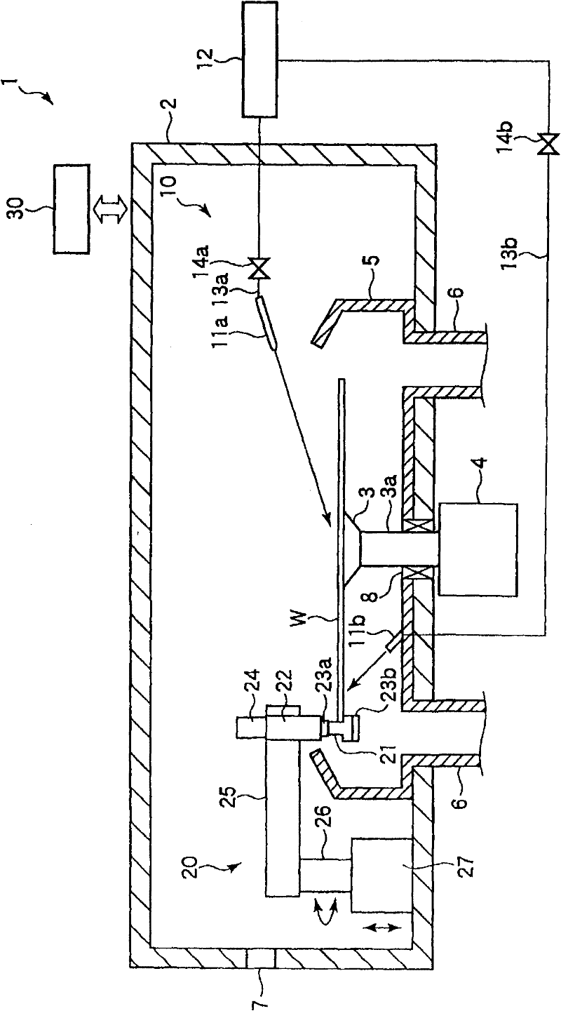
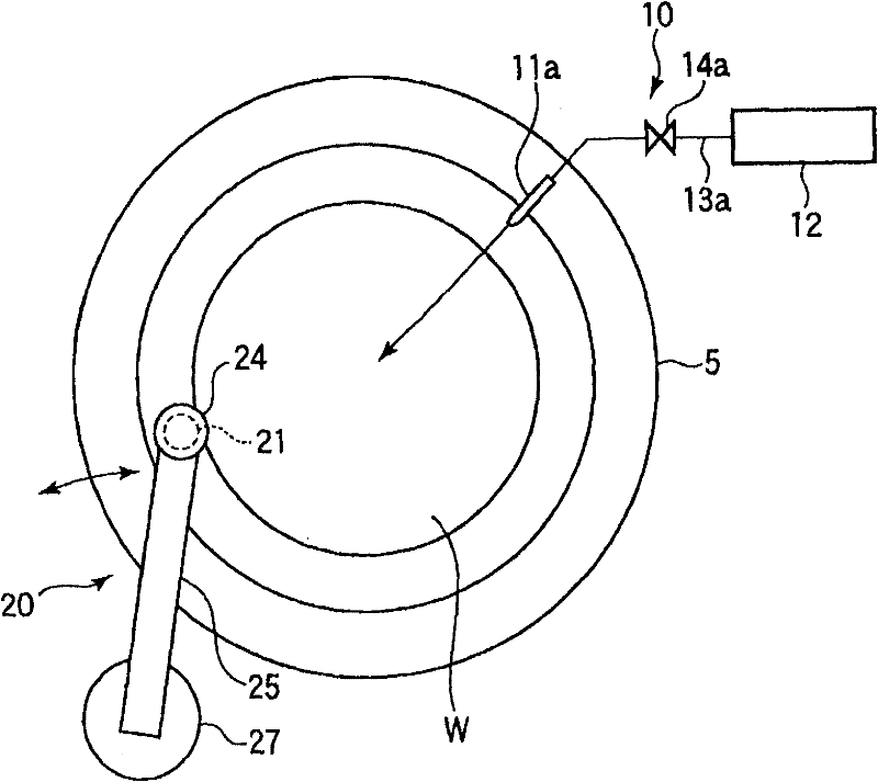
[0059] A first embodiment of the present invention will be specifically described below with reference to the drawings. figure 1 It is a schematic diagram showing the structure of the wafer cleaning apparatus according to the first embodiment of the present invention. figure 2 is a floor plan showing its interior.
[0060] The wafer cleaning device 1 has a chamber 2 . The chamber 2 is provided with a spin chuck 3 for suctioning and holding a semiconductor wafer (hereinafter simply referred to as a wafer) W serving as a substrate to be cleaned in a horizontal state by vacuum suction. A motor 4 provided below the chamber 2 can rotate the spin chuck 3 via a shaft 3 a. In addition, a cover 5 is provided in the chamber 2 so as to cover the wafer W held on the spin chuck 3 . At the bottom of the cover 5 , an exhaust and liquid discharge pipe 6 for exhausting and liquid discharge is provided so as to extend downward of the chamber 2 . In the side wall of the chamber 2, a loading...
no. 2 Embodiment
[0081] next reference Figure 11 to Figure 13 A second embodiment of the present invention will be described. In the 2nd embodiment, with Figure 1 to Figure 10 The parts that are the same as those in the first embodiment shown are assigned the same symbols, and detailed descriptions thereof will be omitted.
[0082] In this example, Figure 5 The function of controlling the cleaning of the wafer W by changing the compressive force against the brush 21 and controlling the cleaning of the wafer W by the control unit 30 shown in . That is, based on the processing plan stored in the storage unit 63, the controller 61 sends a command to the air cylinder 24 to change the compressive force of the pressing members 23a and 23b on the brush 21 to control cleaning of the wafer W. Specifically, it is possible to control the cleaning of the wafer W by changing the compressive force of the brush in real time during cleaning. Alternatively, it is possible to obtain information on the st...
no. 3 Embodiment
[0097] next reference Figure 14 to Figure 20 A third embodiment of the present invention will be described. In the 3rd embodiment, with Figure 1 to Figure 10 The parts that are the same as those in the first embodiment shown are assigned the same symbols, and detailed descriptions thereof will be omitted.
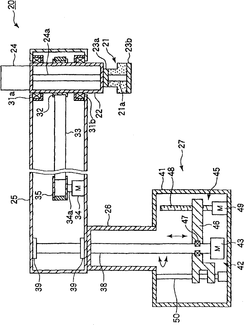
[0098] like Figure 14 As shown, the cleaning mechanism 20 has a brush 21 formed of a spongy resin for cleaning the peripheral portion including the end surface of the wafer W, a rotation support member 22 that supports the brush 21 in a rotatable manner, and a brush holding mechanism that holds the brush 21 ( brush compression mechanism) 23, a cylinder 24 for applying a holding force for holding the brush 21 or a compressive force for compressing the brush 21, a rotating arm 25 for rotating the brush 21, and a built-in shaft portion 26 used as a rotating shaft of the rotating arm 25 , and a rotating lifter 27 built in a rotating mechanism that rotates the rotating arm...
PUM
 Abstract
Description
Claims
Application Information
 - R&D
- Intellectual Property
- Life Sciences
- Materials
- Tech Scout
- Unparalleled Data Quality
- Higher Quality Content
- 60% Fewer Hallucinations
Browse by: Latest US Patents, China's latest patents, Technical Efficacy Thesaurus, Application Domain, Technology Topic, Popular Technical Reports.
© 2025 PatSnap. All rights reserved.Legal|Privacy policy|Modern Slavery Act Transparency Statement|Sitemap|About US| Contact US: help@patsnap.com


