Gas liquefying process for mixed refrigerant and mixed refrigerant
A technology of mixing refrigerants and refrigerants, applied in refrigeration and liquefaction, gas/liquid distribution and storage, liquefaction, etc., can solve the problems of long start-up time, many units, abnormal operation, etc., to achieve flexible load adjustment, safe and reliable operation , The effect of load adjustment is convenient
- Summary
- Abstract
- Description
- Claims
- Application Information
AI Technical Summary
Problems solved by technology
Method used
Image

Examples
Embodiment 1
[0033] [Example 1] Coal bed gas liquefaction
[0034] Purified coalbed methane components after deacidification and dehydration (mole percent): Nitrogen 2.0843%, Methane 97.901%, Ethane 0.0053%, Propane 0.0001%, Others 0.0093%. Pressure: 4.46MPa Temperature: 38°C.
[0035] CBM liquefaction process:
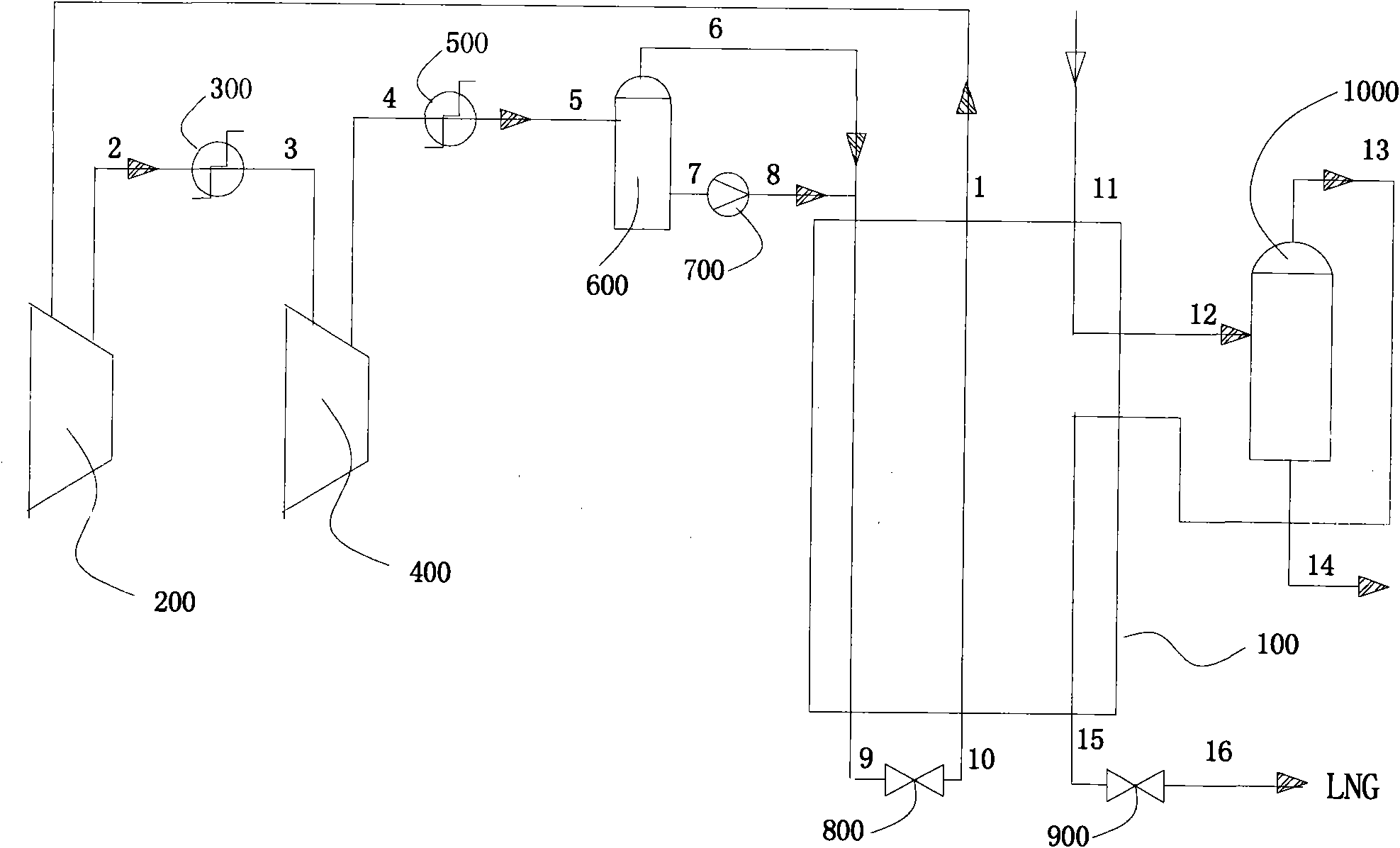
[0036] The purified layer gas 11 enters the cold box 100 for pre-cooling, and the coal bed gas 12 pre-cooled to -70°C exits the cold box and enters the heavy hydrocarbon separator 1000, and the heavy hydrocarbon 14 is discharged from the bottom of the heavy hydrocarbon separator, and its flow rate is zero, that is, there is no heavy hydrocarbon Precipitate. The gas phase 13 from the top of the heavy hydrocarbon separator enters the cold box 100 for deep cooling, and the supercooled liquid 15 cooled to -150°C goes out of the cold box, and is throttled and reduced to 0.4MPa by the throttle valve 800, and the low-pressure supercooled liquid 16 enters the LNG storage unit.
[003...
Embodiment 2
[0040] [Example 2] North Sea natural gas liquefaction
[0041] Purified natural gas components after deacidification and dehydration (mole percentage): nitrogen 1.5%, methane 77%, ethane 14.5%, propane 3%, n-hexane 4%, pressure: 4.97MPa, temperature: 38°C.
[0042] CBM liquefaction process:
[0043] The purified layer gas 11 enters the cold box 100 for pre-cooling, the coal bed gas 12 pre-cooled to -35°C exits the cold box and enters the heavy hydrocarbon separator 1000, and the heavy hydrocarbon 14 is discharged from the bottom of the heavy hydrocarbon separator. The gas phase 13 coming out of the top of the heavy hydrocarbon separator enters the cold box 100 for cryogenic cooling, the supercooled liquid 15 cooled to -140°C comes out of the cold box, is throttled and reduced to 0.6MPa by the throttle valve 800, and the cryogenic liquid 16 enters the LNG storage unit .
[0044] Refrigerant cycle process:
[0045] The 31°C low-pressure gaseous mixed refrigerant 1 exits the c...
Embodiment 3
[0047] [Example 3] Jilin Natural Gas Liquefaction
[0048] Purified CBM components after deacidification and dehydration (mole percent): nitrogen 3.42%, methane 94.55%, ethane 1.22%, propane 0.09%, butane 0.37%, n-pentane 0.18%, other 0.17%, pressure: 3.97MPa , Temperature: 38°C.
[0049] Weather liquefaction process:
[0050] The purified layer gas 11 enters the cold box 100 for pre-cooling, the coal bed gas 12 pre-cooled to -70°C exits the cold box and enters the heavy hydrocarbon separator 1000, and the heavy hydrocarbon 14 is discharged from the bottom of the heavy hydrocarbon separator. The gas phase 13 coming out of the top of the heavy hydrocarbon separator enters the cold box 100 for cryogenic cooling, the supercooled liquid 15 cooled to -156°C comes out of the cold box, and is throttled and reduced to 0.12MPa by the throttle valve 800, and the cryogenic liquid 16 enters the LNG storage unit .
[0051] Refrigerant cycle process:
[0052] 30°C low-pressure gaseous...
PUM
 Abstract
Description
Claims
Application Information
 - R&D
- Intellectual Property
- Life Sciences
- Materials
- Tech Scout
- Unparalleled Data Quality
- Higher Quality Content
- 60% Fewer Hallucinations
Browse by: Latest US Patents, China's latest patents, Technical Efficacy Thesaurus, Application Domain, Technology Topic, Popular Technical Reports.
© 2025 PatSnap. All rights reserved.Legal|Privacy policy|Modern Slavery Act Transparency Statement|Sitemap|About US| Contact US: help@patsnap.com