
Automatic gain vehicle active antenna amplifier

An active antenna, automatic gain technology, applied in high-frequency amplifiers, gain control, amplification control and other directions, can solve the problems of large circuit boards, inability to achieve stable signal output, complex circuits, etc., to achieve stable output signals, improve Dynamic range, the effect of simplifying the production process

Inactive Publication Date: 2009-12-16
HEFEI BANGLI ELECTRONICS
View PDF0 Cites 5 Cited by
  • Summary
  • Abstract
  • Description
  • Claims
  • Application Information

AI Technical Summary

Problems solved by technology

At present, the more common automotive antenna amplifiers mainly use discrete components to achieve the amplification gain of the antenna signal. The circuit board is large in size and the circuit is complicated, which cannot achieve stable signal output under the conditions of rapid signal strength changes during vehicle operation.

Method used

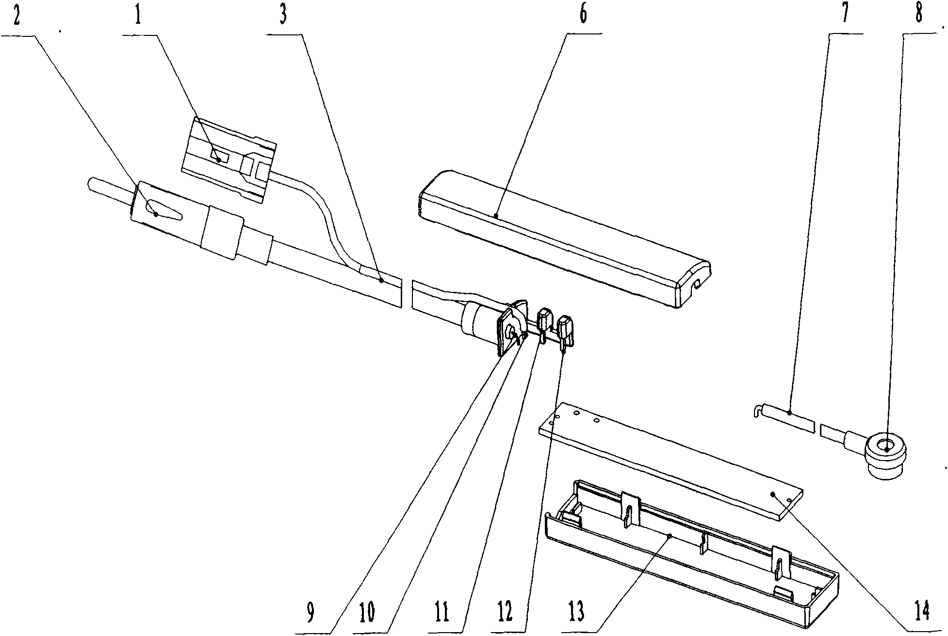

Image

  • Automatic gain vehicle active antenna amplifier
  • Automatic gain vehicle active antenna amplifier
  • Automatic gain vehicle active antenna amplifier

Examples


Embodiment Construction

[0021] The present invention will be further described below in conjunction with the accompanying drawings.

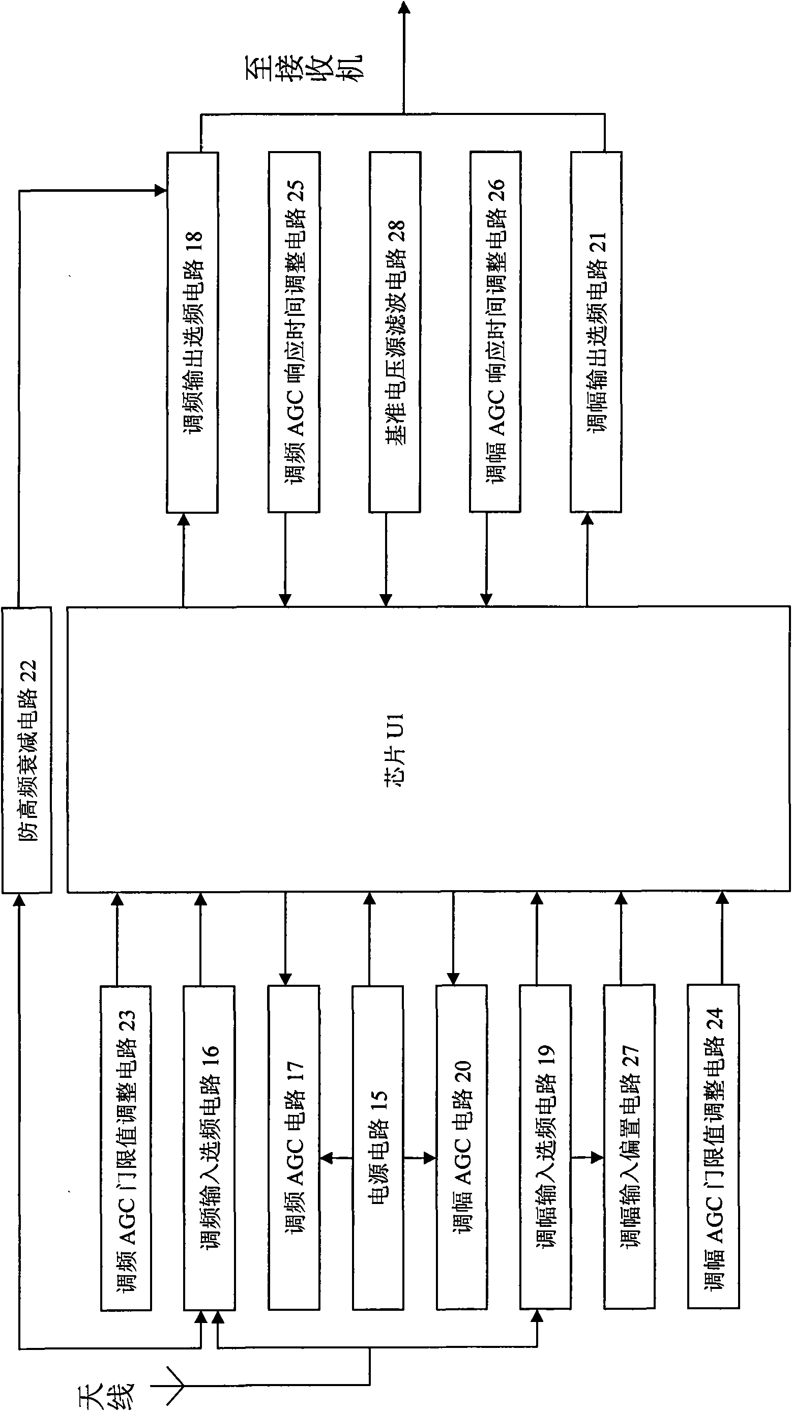
[0022] 1, the circuit block diagram of the present invention is as image 3 as shown,

[0023] Automatic gain vehicle-mounted active antenna amplifier, including power supply circuit 15, FM input frequency selection circuit 16, FM AGC circuit 17, FM output frequency selection circuit 18, AM input frequency selection circuit 19, AM AGC circuit 20, AM output frequency selection circuit 21 , anti-high frequency attenuation circuit 22, frequency modulation AGC threshold value adjustment circuit 23, amplitude modulation AGC threshold value adjustment circuit 24, frequency modulation AGC response time adjustment circuit 25, amplitude modulation AGC response time adjustment circuit 26, amplitude modulation input bias circuit 27, reference Voltage source filter circuit 28, chip U1;

[0024] The antenna output is connected to the chip U1 through the frequency modulation input...


PUM


Abstract

The invention relates to an automobile antenna amplifier, in particular to an automatic gain vehicle active antenna amplifier. The amplifier comprises a chip for realizing the automatic gain control logical operation of a signal, a frequency selection circuit for processing a frequency modulation signal and an amplitude modulation signal respectively, an AGC circuit, an AGC threshold value adjusting circuit and an AGC response time adjusting circuit; and the automatic gain vehicle active antenna amplifier utilizes automatic gain control to eliminate voltage error between the output signal amplitude of the antenna amplifier and the needed output signal amplitude, improves the dynamic range of the amplifier to make the output signal stable and reception clear, overcomes the disadvantages of the unstable signal of the prior art and is free from distorting even if the amplifier is in extreme environment with rapidly-changed signal strength.

Description

technical field [0001] This product relates to a car antenna amplifier, which is suitable for car radio signal receiving system. Background technique [0002] Car radio antennas are developing towards small and miniature designs. Due to the reduction in antenna size and the lengthening of signal cables, the reception effect of car radios will inevitably be affected, so car antenna amplifiers have emerged as the times require. At present, the more common automotive antenna amplifiers mainly use discrete components to achieve the amplification gain of the antenna signal. The circuit board is large in size and the wiring is complex, which cannot achieve stable signal output under the conditions of rapid signal strength changes during vehicle operation. Contents of the invention [0003] The technical problem to be solved by the present invention is to provide a vehicle-mounted active antenna amplifier with an automatic gain function. [0004] The technical scheme adopted in ...

Claims


Application Information

Patent Timeline
IPC IPC(8): H03F3/19H03G3/20H04B1/16
Inventor 张肖康周革
Owner HEFEI BANGLI ELECTRONICS
Learn More