


Quick Research
Generate reliable direction feasibility study reports for your R&D in just a few steps.

Technical Q&A
Discover and master advanced knowledge NOW. Basics, ideas, possibilities, all at once.

Find Solutions
As an expert in R&D theories, this can generate solutions to your technical problems instantly.

Evaluate Feasibility
Analyze your overall solution with one click, know your potential R&D risks in advance.

Monitor Landscape
Get weekly tech updates, stay abreast of the latest tech innovations and key insights.
Structure for electromagnetic shielding between panels and manufacturing method thereof
An electromagnetic shielding structure and electromagnetic shielding technology, applied in the fields of magnetic field/electric field shielding, electrical components, chassis/cabinet/drawer parts, etc., can solve problems such as increasing manufacturing costs, improve quality, reduce deformation, Strength-enhancing effect
- Summary
- Abstract
- Description
- Claims
- Application Information
AI Technical Summary
Problems solved by technology
Method used
Image

Examples
no. 1 example
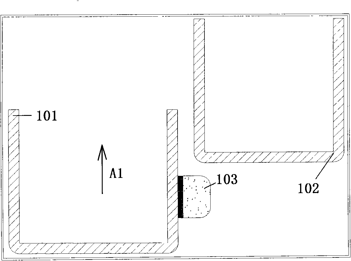
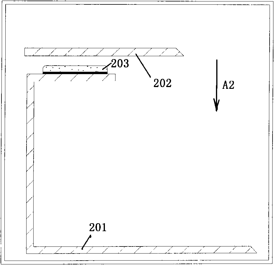
[0040] Figure 4 A perspective exploded view of a structure 1 for electromagnetic shielding between panels according to the present invention is shown. Figure 5 is a schematic diagram of the hemming process according to the present invention. Image 6 is a top view of a structure 1 for electromagnetic shielding between panels according to the present invention. like Figure 4 As shown, a structure for electromagnetic shielding between panels is provided, including: a first panel 23 and a second panel 4 oppositely arranged; and electromagnetic shielding arranged between the first and second panels 23, 4 The component 10, wherein: the first panel 23 is provided with a groove 3, and the electromagnetic shielding component 10 is accommodated in the groove 3.
[0041] Specifically, in Figure 4 Among them, the structure 1 includes a first wall 21 , a second wall 22 connected to the first wall 21 and a first panel 23 . In this embodiment, the first panel 23 is formed to be con...
no. 2 example
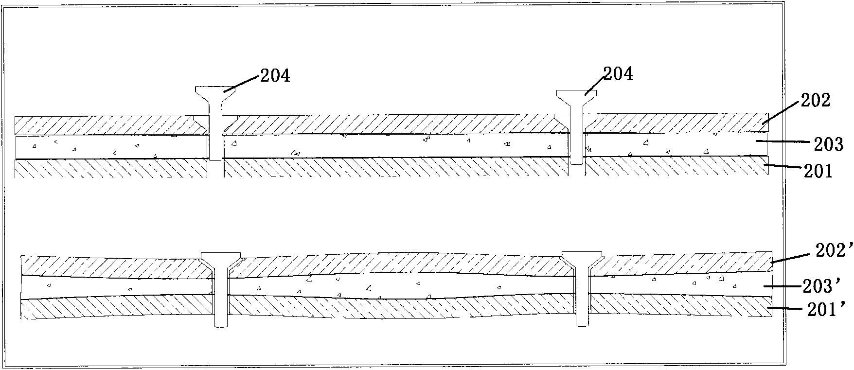
[0052] Figure 8 A schematic diagram of a single-disk plugging device 1' to which the structure 1 for electromagnetic shielding between panels according to the present invention is applied is shown. like Figure 8 As shown, a structure for electromagnetic shielding between panels is provided, including: a first panel 20 and a second panel 20' arranged oppositely; The electromagnetic shielding member 10, wherein: the first panel 20 is provided with a groove 3, and the electromagnetic shielding member 10 is accommodated in the groove 3.
[0053] It should be noted that, for the sake of brevity, structures similar to those in the first embodiment will not be described in the second embodiment. Meanwhile, components identical or similar to those in the first embodiment are denoted by similar symbols to those in the first embodiment.
[0054] In the single-disk insertion and removal device 1', the second panel 4 is the back panel of another single-disk insertion and removal devi...
PUM
 Abstract
Description
Claims
Application Information
 - R&D Engineer
- R&D Manager
- IP Professional
- Industry Leading Data Capabilities
- Powerful AI technology
- Patent DNA Extraction
Browse by: Latest US Patents, China's latest patents, Technical Efficacy Thesaurus, Application Domain, Technology Topic, Popular Technical Reports.
© 2024 PatSnap. All rights reserved.Legal|Privacy policy|Modern Slavery Act Transparency Statement|Sitemap|About US| Contact US: help@patsnap.com