
Power system

A technology of power supply system and AC power supply, which is applied in the direction of control/regulation system, electrical components, and adjustment of electric variables, etc., and can solve the problems such as the difficulty in realizing the miniaturization of the transformer 10, the increase of power loss of the power supply unit, and the increase of input current, etc. Achieve the effect of significantly reducing power loss, reducing power consumption, and reducing power loss

Inactive Publication Date: 2009-12-02
KAGA ELECTRONICS CO LTD
View PDF2 Cites 5 Cited by
  • Summary
  • Abstract
  • Description
  • Claims
  • Application Information

AI Technical Summary

Problems solved by technology

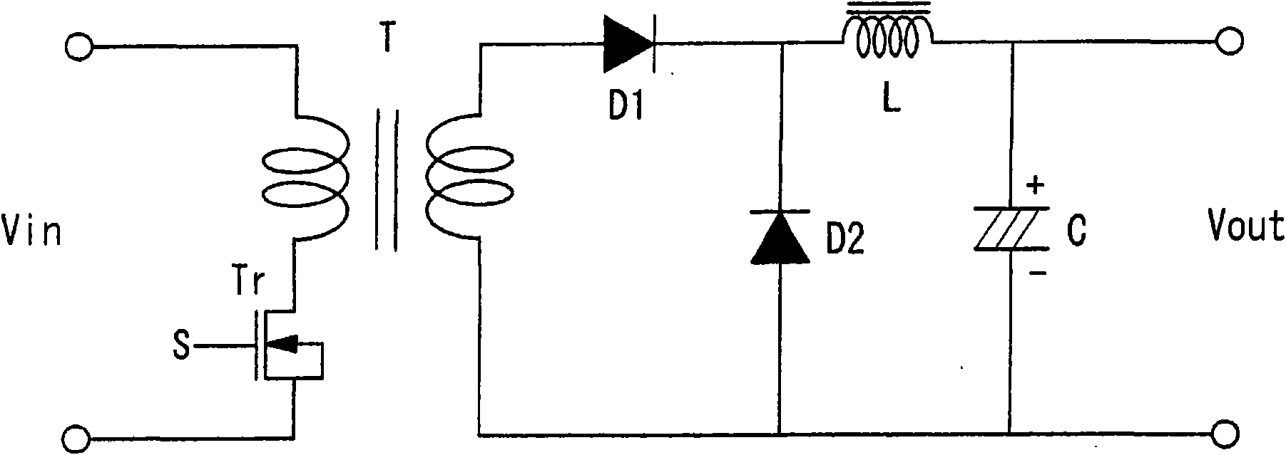
[0016] in such as image 3 In the power supply system shown, since the transformer 10 is connected to a plurality of power supply units, the input current of the transformer 10 increases correspondingly as the number of power supply units increases. As a result, it is difficult to miniaturize the transformer 10, and the cost will improve
[0017] On the other hand, the diode D used for rectification of each power supply unit 20-26 produces a forward voltage drop
Assuming this voltage drop is about 0.9V, a power loss of 0.9V x 4Ia
As shown above, if the power factor is not improved, in a power supply unit, the loss power, so the overall power loss of the power supply unit is also significantly increased
Especially if the voltage or current of the input AC power source increases, a large amount of power will be lost correspondingly, so it must not be ignored

Method used


Image

  • Power system
  • Power system
  • Power system

Examples


Embodiment

[0059] Figure 4 is a diagram showing the configuration of a power supply system according to an embodiment of the present invention. The power supply system 100 has an isolation type power transformer 110 and a plurality of power supply units 200 - 1 to 200 - n (n is a natural number) connected to the power transformer 110 . The isolated power transformer 110 preferably inputs commercial AC100V AC power at the primary side, and outputs AC24V AC power at the secondary side. On the secondary side of the power transformer 110, n power supply units 200-1 to 200-n are connected, and the power supply units 200-1 to 200-n are respectively supplied with AC power of AC24V. Such a power supply system is used, for example, in pachinko halls, each game machine having a power supply unit.

[0060] The internal structures of the plurality of power supply units 200-1 to 200-n are substantially the same, so only the power supply unit 200-1 will be described here. The power supply unit 200...


PUM


Abstract

The invention provides a power system that can improve power factor and power loss, and realize miniaturization of a transformer comparing to the past, wherein the power system (100) comprises the following components: a power transformer (110) that can change AC100V to AC24V; and a plurality of power source units (200-1 to 200-n) connected to the power transformer (110). The power source units (200-1 to 200-n) comprises the following components: a rectification circuit (210) that rectifies the AC24v through a synchronous rectifier bridge; a power factor improving circuit (220) that improves power factor to voltage after rectification; and an output circuit (230) that outputs the direct current voltage. The power factor improving circuit (220) comprises an induction coil L, a FET (1), a FET (2), and a control circuit (222) that controls the switch of the FET (1) and the FET (2), wherein the control circuit (222) adjusts dutyfactor of the FET (1) and the FET (2) so as to make the expected DC voltage output from the output circuit (230).

Description

technical field [0001] The present invention relates to a power supply system for supplying alternating current from one alternating current power supply to a plurality of power supply units, and particularly relates to the improvement of power loss and power factor in the power supply units. Background technique [0002] With the miniaturization and integration of semiconductor devices and electronic devices, driving power sources for internal power supplies of these devices and devices have become diverse. For example, in semiconductor devices such as CPUs and memories, circuit wiring widths have been miniaturized in order to achieve high-density integration, and the drive voltage has been reduced from 5V to 3.3V and 1.8V along with this. In addition, in electronic equipment such as mobile phones, computers, OA equipment, in-vehicle electronic equipment, and game machines, there are cases where the driving voltages for driving liquid crystal displays, audio equipment, reco...

Claims


Application Information

Patent Timeline
Patent Type & Authority Applications(China)
IPC IPC(8): H02M3/28H02M3/335H02M1/42
CPCY02B70/126Y02B70/10
Inventor 内尾诚一郎
Owner KAGA ELECTRONICS CO LTD
Learn More