
Tension-compression and fatigue loading testing machine based on laser confocal microscope

A laser confocal and fatigue loading technology, applied in the direction of applying stable tension/pressure to test the strength of materials, using optical devices, measuring devices, etc., can solve the problems of small observation range, complicated operation process, loss of test piece information, etc. Achieve the effect of improving precision and automation

Inactive Publication Date: 2009-12-02
TSINGHUA UNIV
View PDF0 Cites 30 Cited by
  • Summary
  • Abstract
  • Description
  • Claims
  • Application Information

AI Technical Summary

Problems solved by technology

[0004] The existing common loading devices under high-resolution microscopes are mainly the loading devices under the scanning electron microscope (an electron microscope) and the loading device under the atomic force microscope (a scanning probe microscope). The problems and defects in them are mainly There are: first, the scanning electron microscope needs to make measurements in a vacuum environment, the operation process is complicated, and the loaded specimens and loading methods are limited; the second is that the scanning electron microscope can only observe conductors, and gold plating is required for non-conductors, but often loses The information on the surface of the specimen, such as using the moiré method to test, will damage the preset grating on the surface of the specimen; the third is that the observation range of the atomic force microscope is very small, and the roughness of the surface of the object and the deformation of the object can only be limited to the nanometer level. range, unable to cope with the loading of common specimens

Method used

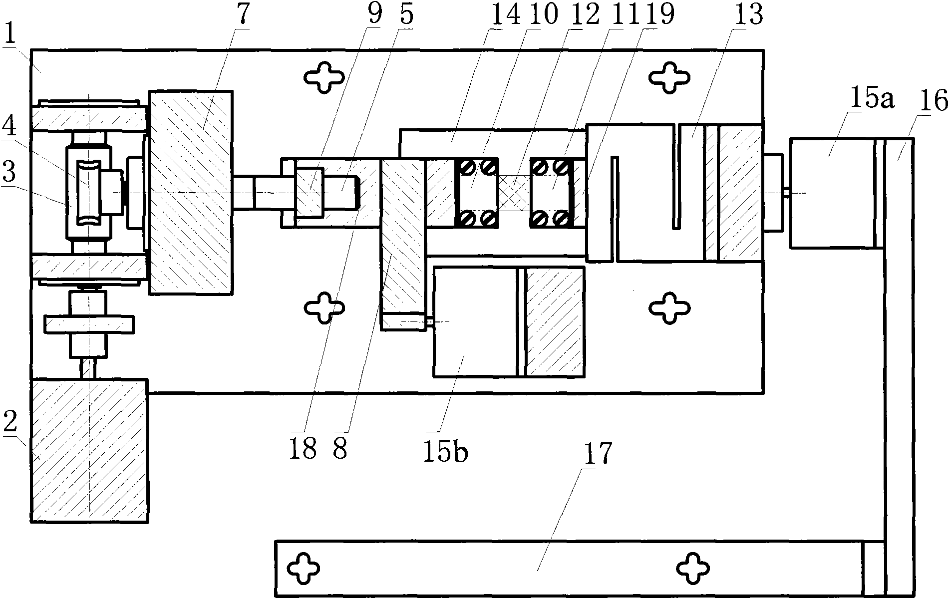

Image

  • Tension-compression and fatigue loading testing machine based on laser confocal microscope
  • Tension-compression and fatigue loading testing machine based on laser confocal microscope
  • Tension-compression and fatigue loading testing machine based on laser confocal microscope

Examples


Embodiment

[0036] Measuring the deformation of metal specimens under tensile loading using the phase-shift moiré method

[0037] Make a typical metal test piece, its shape is as image 3 As shown, it can also be slightly changed according to needs. Paste a holographic orthogonal grating with 1200 lines / mm on the surface of the metal test piece, put it into the two holders of the loading device, and tighten the screws on the holder to fix the test piece. The nut 9 is disconnected from the slider 19, and the first piezoelectric ceramic 15a is placed. Then use the stepper motor controller to control the stepper motor 2 to load, read out the force load result with the force load display of the force sensor 13, load in sections, and collect images at the end of each loading. When collecting images, it is necessary to set the scanning line width of the laser scanning confocal microscope to about 0.833um, which is close to the grating pitch of 1200 lines / mm. Moire streaks will be produced. ...


PUM


Abstract

The invention relates to a tension-compression and fatigue loading testing machine based on a laser confocal microscope, and in particular provides a loading testing machine applicable to a laser confocal microscope platform. The testing machine comprises a fixed base plate, a tension-compression loading device driven by a motor, a fatigue loading device driven by a piezoelectric ceramic, a force sensor, a holding device, a phase-shifting device and the like. The testing machine can perform tension-compression and fatigue loading tests on a typical sample and a film of a metal or non-metal material under macroscopic scale uniaxial stress, and designs the phase-shifting device for an optical testing method for improving the test accuracy and the automation degree. The testing machine has a compact structure, and a test piece is abutted on the lower bottom surface of the testing machine so that the loading under the laser confocal microscope platform can be achieved; besides, the testing machine uses the microscope to collect loading images, and process the images by an optical method to obtain mechanical parameters of a test piece material. The testing machine has the advantages of high system measurement sensitivity, reliable result and wide application range.

Description

technical field [0001] The invention relates to a loading test machine for testing static and dynamic mechanical properties of typical samples and films of metal or non-metallic materials under uniaxial stress on a macro scale, and is especially suitable for a special loading test machine under a laser scanning confocal microscope , belongs to the technical field of experimental mechanical devices. Background technique [0002] The study of the mechanical properties of materials has always been a concern in various engineering fields such as mechanics, machinery, and civil engineering. The most common test method for mechanical parameters is the uniaxial tensile method, which is the most direct way to measure elastic modulus, Poisson's ratio, yield strength and fracture strength. With the development of experimental mechanics, some typical optical testing methods, such as moiré method and digital speckle correlation method, have been applied to high-resolution microscopes, ...

Claims


Application Information

Patent Timeline
IPC IPC(8): G01N3/08G01N3/04G01B11/16
Inventor 谢惠民王庆华唐敏锦张建民戴福隆
Owner TSINGHUA UNIV
Learn More