
Worm fan structure for preventing revolving air flow and reflux

A technology of rotating air flow and fan, which is applied to parts of pumping devices for elastic fluids, non-variable pumps, machines/engines, etc. It can solve the problem of efficiency or performance degradation, easy generation of rotating air flow, and increased air flow noise, etc. problems, to achieve the effect of eliminating airflow noise and leakage loss, lengthening the return distance, and increasing the resistance

Inactive Publication Date: 2009-12-02
LG ELECTRONICS (TIANJIN) APPLIANCES CO LTD
View PDF0 Cites 6 Cited by
  • Summary
  • Abstract
  • Description
  • Claims
  • Application Information

AI Technical Summary

Problems solved by technology

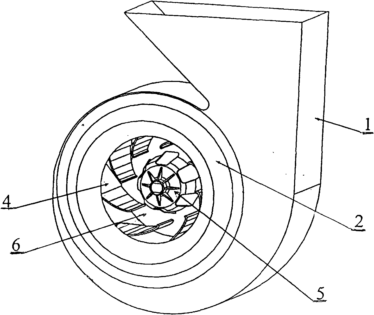
[0008] The fan of the existing cabinet-type air conditioner indoor unit is a worm gear fan (TURBO) in the centrifugal fan. Its structure includes: a front plate welded to the fan blade, a rear plate, and a hub connected to the rear plate, and the pivot is fixed to the through hole in the center of the hub. , the casing is fixed to the volute and the fan motor on the rear wall of the air conditioner, installed in front of the front plate of the fan blade, and the collector of the air inlet of the volute, which produces a larger fan than the forward multi-blade centrifugal fan (Sirocco) Air volume and fan efficiency, however, the radial cross-sectional view of the existing worm gear fan ring-shaped collector is an upward convex arc line covering the edge of the air inlet of the front disk, and the diameter of the upward convex arc line is relatively large. The gap between the concave arc-shaped front panel and the convex arc-shaped current collector is relatively large. On the one hand, it is easy to generate swirling airflow, resulting in increased airflow noise; on the other hand, there is leakage loss, resulting in a decrease in efficiency or performance

Method used


Image

  • Worm fan structure for preventing revolving air flow and reflux
  • Worm fan structure for preventing revolving air flow and reflux
  • Worm fan structure for preventing revolving air flow and reflux

Examples


Embodiment Construction

[0035] To further illustrate the present invention's content, technical solutions, and structural features, the following examples are given and described below in conjunction with the accompanying drawings:

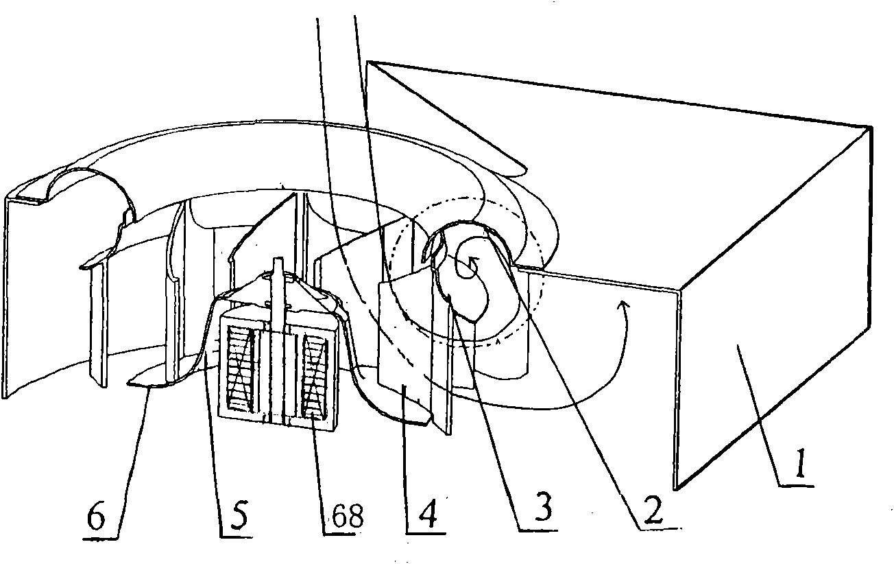
[0036] Figure 5 It is a radial sectional view of the worm gear fan structure of the present invention and a drawing in which the rotating airflow is blocked by an upward convex arc, a downward concave arc, a downward concave U-shaped arc surface and a baffle;

[0037] Figure 6 for Figure 5 Enlarged view of the part in the circle.

[0038] Such as Figure 5-6 As shown, the structure of the worm gear fan for preventing the rotating airflow and backflow of the present invention includes: the front disc 3 and the rear disc 6 welded to the fan blade 4; the hub 5 connected to the rear disc 6 and the fan blade 4; the pivot is fixed on the hub 5 The central through hole, the casing is fixed on the volute 1 and the fan motor 68 on the rear wall of the air conditioner; it i...


PUM


Abstract

The invention relates to a fan of an air conditioner, in particular to a worm fan structure for preventing revolving air flow and reflux, which solves the problem that a radial sectional view of a flow collector of the existing worm fan is a convex arc line which is covered on the edge of an air inlet of a front disk of the fan and provided with a large gap with the edge so as to ensure that the air flow entering the air inlet of the fan forms the revolving air flow between the arc front disk and the arc flow collector under the centrifugal effect of a fan blade, thus air flow noise and leakage loss are generated, thereby reducing properties such as the blowing rate, the wind speed, and the like of the fan. The invention adopts the technical scheme that the worm fan comprises the front disk, a rear disk, a wheel hub, a central through hole, a machine shell, a fan motor and the flow collector, wherein the front disk and the rear disk are welded on the fan blade; the wheel hub is connected to the rear disk and the fan blade; a pivot is fixed at the central through hole of the wheel hub; the machine shell is fixed at a warm shell; the fan motor is arranged on the back wall of an air conditioner; and the flow collector is arranged on the air inlet of the worm shell of the fan in front of the fan blade. The worm fan is characterized in that the radial sectional view of the flow collector comprises the convex arc line, a concave arc line, a concave U-shaped arc line and a baffle plate line. The worm fan is used for the air conditioner for reducing the air flow noise and improving equipment performance.

Description

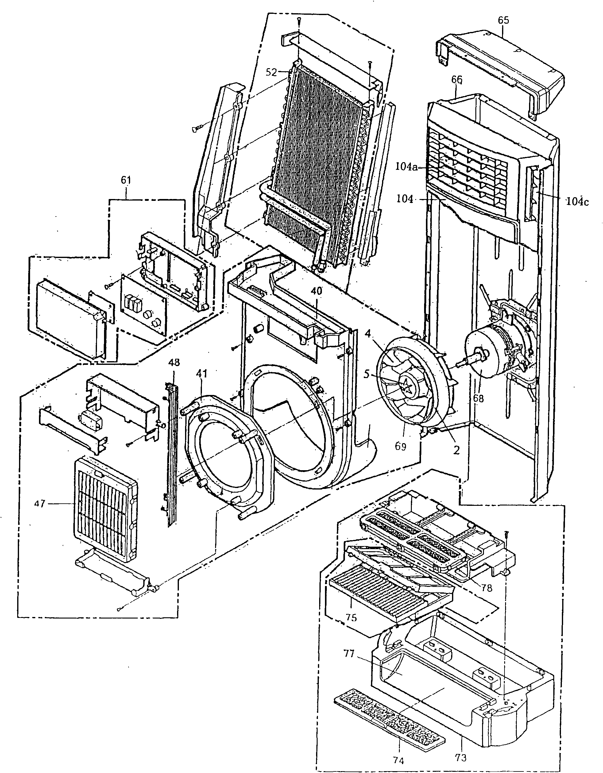
technical field [0001] The invention relates to air conditioning technology, in particular to a turbo fan structure for preventing rotating airflow and backflow. Background technique [0002] Generally, in order to provide users with a more comfortable environment, the air conditioner utilizes a compressor; ; The air circulation loop formed by the fan cools and heats or purifies the air indoors, and is roughly divided into split type and integral type. [0003] The split type and the integral type have the same function, but the split type is to install a cooling or heat release device in the indoor unit, and set up a heat release or cooling and compression device in the outdoor unit; the integral type is to integrate the cooling or heat release function , Drill holes in the walls of the house or install directly on the windows. [0004] The structure exploded view of the existing split cabinet type air conditioner indoor unit is as follows: figure 1 As shown, it includes...

Claims


Application Information

Patent Timeline
Patent Type & Authority Applications(China)
IPC IPC(8): F04D29/66F04D29/00
Inventor 黄章峰
Owner LG ELECTRONICS (TIANJIN) APPLIANCES CO LTD
Learn More