Up-mounting type plastic ball-valve

A technology for plastic ball valves and top loading, applied in the field of plastic ball valves, which can solve problems such as manufacturing and assembly difficulties, affecting pre-tightening force, small pre-tightening force of sealing surface, etc., and achieves the effect of avoiding welding process

Active Publication Date: 2009-11-25
GUANGDONG LIANSU VALVE CO LTD
View PDF0 Cites 0 Cited by
  • Summary
  • Abstract
  • Description
  • Claims
  • Application Information

AI Technical Summary

Problems solved by technology

However, this structure achieves the design pressing force through two buckles located on the three parts, which brings great difficulties to manufacturing and assembly;
[0007] 2. The socket depth of the valve body and the connecting seat directly affects the axial distance between the two sealing surfaces and affects the pre-pressing force
The socket depth is large, the pre-tightening force is large, the torque to open and close the valve is large, and the wear on the sealing surface is large; the socket depth is small, the sealing surface pre-tightening force is small, and there is a hidden danger of internal leakage
Moreover, it is difficult to ensure that the centerlines of the valve body and the connecting seat coincide during the socketing process. The frequent phenomenon is that the two centerlines do not coincide and form a certain angle, so that the pressing force of the sealing ring and the ball is in the entire sealing belt uneven;
[0008] 3. From a manufacturing point of view, since the two sealing rings are respectively located on the valve body and the connecting seat, the process positioning surfaces of the processing sealing ring installation rings are respectively located on these two parts. Therefore, after the assembly of the two sealing ring installation rings There is a certain error in the axial distance due to the manufacture of the positioning surface

Method used


Image

  • Up-mounting type plastic ball-valve
  • Up-mounting type plastic ball-valve
  • Up-mounting type plastic ball-valve

Examples


Embodiment Construction

[0031] The present invention will be further described below in conjunction with the accompanying drawings.

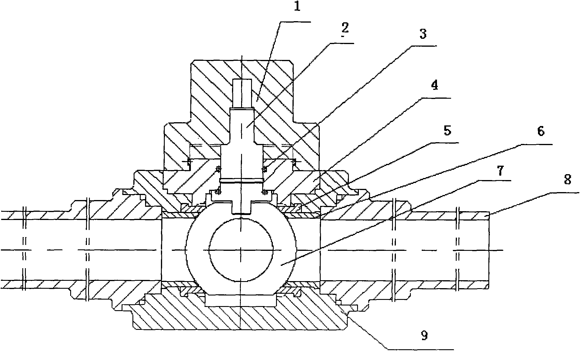
[0032] Refer to attached figure 1 The overall structure diagram of the PE ball valve shown. The plastic ball valve of the present invention is composed of a valve stem cap 1, a valve stem 2, a valve stem sealing ring 3, a valve cover 4, a valve ball sealing ring 5, a valve ball sealing ring support ring 6, a valve ball 7, a connecting pipe 8, and a valve body 9 .

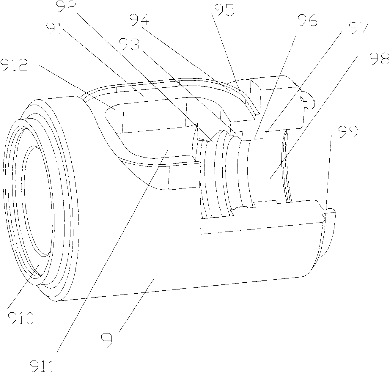
[0033] Refer to attached figure 2The structure diagram of the PE ball valve body shown. The valve body 9 is generally a cylinder with a series of cylindrical holes in it. These cylindrical holes communicate with each other, and their axes coincide with the axis of the cylinder of the valve body. The valve body 9 includes a bonnet melt surface 91, a bonnet annular positioning surface 94, a bonnet axial locating surface 95, an inner cylindrical surface 92 matched with the valve ball sealing ring 5, a valv...


PUM


Abstract

The invention provides an up-mounting type plastic ball-valve, including a valve thimble (1), a valve spindle (2), a valve spindle sealing ring (3), a valve ball sealing ring (5), a valve ball sealing ring support ring (6), a valve ball (7), a pipe connection (8), and a valve body (9), wherein the valve body (9) is provided with a hollow valve ball chamber (911) inside, the valve body (9) is provided with a valve cap hole (912) above the valve ball chamber (911) rightly, a width of the valve cap hole (912) is more than a diameter of the valve ball (7), the ball valve also includes a valve cap (4), the valve cap (4) is provided with a valve spindle axle hole (410) for the valve spindle (2) to pass through, the valve cap (4) is relative to the valve cap hole (912), and the valve cap (4) covers the valve cap hole (912) and is in a butt fusion with the valve body (9) mutually.

Description

technical field [0001] The invention belongs to the field of plastic ball valves, in particular to a top-mounted plastic ball valve. technical background [0002] With the widespread use of plastic gas pipelines, the United States took the lead in developing and producing plastic ball valves, which are widely used in plastic gas pipeline systems. People gradually realize the superiority of plastic ball valves in terms of performance / price, and gradually begin to use plastic ball valves instead of metal ball valves. [0003] Among the existing plastic ball valves, the small-diameter ball valves are integrally welded by hot-melt welding, and the large-diameter ball valves are welded by electrofusion. The hot-melt welding process is simple, the cost is low, and the precision is relatively low; the electric fusion welding process is complicated and the cost is high. [0004] In the structure of hot-melt welded valves, an integral side-mounted structure is generally used at pre...

Claims


Application Information

Patent Timeline
Patent Type & Authority Applications(China)
IPC IPC(8): F16K5/06F16K27/06F16K27/12
CPCF16K5/0636F16L47/02Y10T137/6038
Inventor 杨继跃黄虹宾
Owner GUANGDONG LIANSU VALVE CO LTD
Why Eureka
Try Eureka