
Gear lubricating device for ball mill

A lubricating device and ball mill technology, applied in grain processing and other directions, can solve the problems of insufficient lubrication, easy dust pollution, waste of external dust, etc., and achieve the effects of advanced design, good lubrication effect and uniform oil injection.

Active Publication Date: 2011-06-15
JINAN HEAVY MACHINERY JOINT STOCK
View PDF0 Cites 0 Cited by
  • Summary
  • Abstract
  • Description
  • Claims
  • Application Information

AI Technical Summary

Problems solved by technology

Due to the poor working environment of the mill, the dust in the mill workshop is easy to pollute the lubricant and damage the lubricating oil film between the gears, resulting in dry friction between the gears or impurities in the oil brought by the large gear to damage the working surface of the gear
If the method of artificially adding lubricant regularly is used, the time interval is not easy to grasp, and since the sealing device of the gear must be opened to add grease, it is likely to cause insufficient lubrication or waste of lubricating quality, and impurities such as external dust are easy to enter the gear cover. Waste a lot of manpower and material resources

Method used


Image

  • Gear lubricating device for ball mill
  • Gear lubricating device for ball mill
  • Gear lubricating device for ball mill

Examples


Embodiment Construction

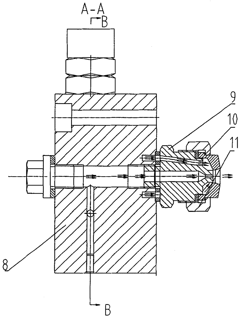
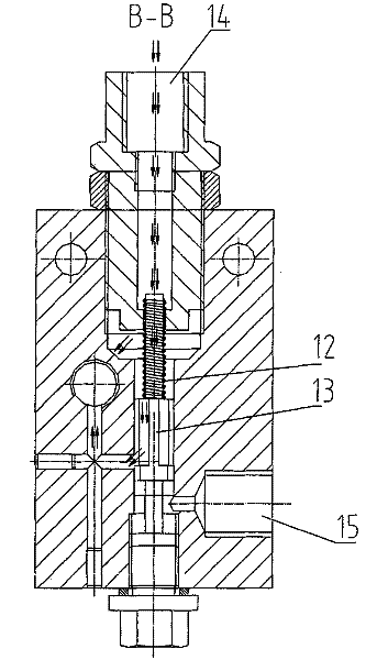
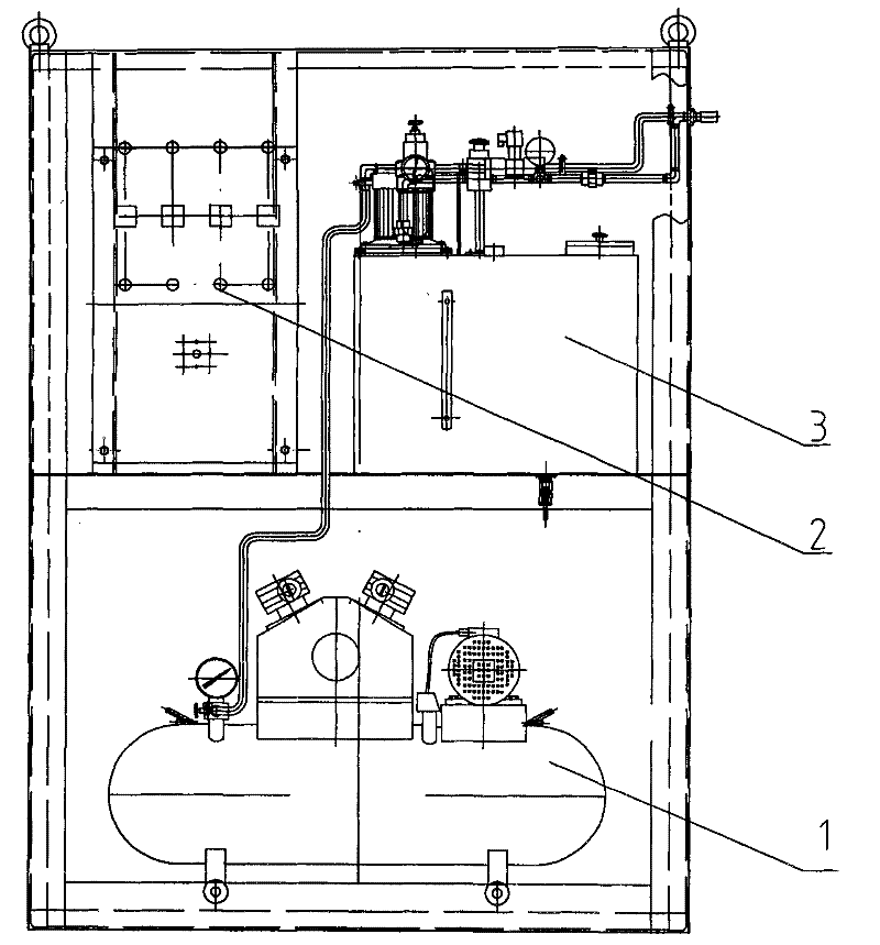
[0020] figure 1 middle, figure 2 , image 3 Among them, it includes a pneumatic system 1 and a hydraulic system 3, both of which are connected to the control system 2, and the pneumatic system 1 includes an air pump, a water separation filter, a solenoid valve, and is connected to the injection plate device 5 through a pipeline 4. The hydraulic system 3 includes a fuel injection pump, a one-way valve, and a pressure regulating valve, and is connected to the injection plate device 5 through a pipeline 4 . The electrical control system 2 is a single-chip microcomputer, which controls the fuel injection pump and the air pump respectively.

[0021] At the same time, the air pressure system 1 and the hydraulic system 3 are respectively connected to the spray plate device 5 through the pipeline 4, and the spray plate device 5 is installed on the gear cover 6 at a position matched with the gear meshing part. The injection plate device 5 is provided with a nozzle 7, the structure ...


PUM


Abstract

The invention discloses a gear lubricating device for a ball mill. The gear lubricating device can spray high-octane lubricating oil fully atomized onto the surface of a gear through a specially designed nozzle to form a complete adhesive oil film; and the nozzle of the gear lubricating device for spraying the lubricating oil is isolated from the external by a gear cover, which not only avoids thedeficient protection on a gear meshing surface by the conventional lubricating method, but also saves a great quantity of manpower and materials. The structure of the gear lubricating device comprises a pressure system and a hydraulic system which are connected with an electric control system, and simultaneously connected with a sprinkler plate device respectively through pipelines; and the sprinkler plate device is arranged on a position of the gear cover matched with a gear meshing part.

Description

technical field [0001] The patent of the present invention relates to a gear lubricating device for a ball mill. Background technique [0002] At present, the lubrication of the gear transmission of the mill is relatively simple. Generally, the large gear cover is used as the oil tank, and the thin oil in the oil tank is driven to lubricate the large and small gears through the rotation of the gears, or the grease is manually added to the meshing parts of the gears at intervals. Due to the poor working environment of the mill, the dust in the mill workshop is easy to pollute the lubricant and damage the lubricating oil film between the gears, resulting in dry friction between the gears or impurities in the oil brought by the large gear to damage the working surface of the gear. If the method of artificially adding lubricant regularly is used, the time interval is not easy to grasp, and since the sealing device of the gear must be opened to add grease, it is likely to cause i...

Claims


Application Information

Patent Timeline
Patent Type & Authority Patents(China)
IPC IPC(8): B02C17/18
Inventor 陈巧云刘延庆
Owner JINAN HEAVY MACHINERY JOINT STOCK
Learn More