Optical disc and optical disc device
An optical disc device and optical disc technology, which are applied to optical recording heads, optical recording carriers, recording/reproducing by optical methods, etc., can solve the problems of not being able to obtain the optimum value of the recording power of the L0 layer, and reduce the recording capacity, Reduce the effect of zooming out
- Summary
- Abstract
- Description
- Claims
- Application Information
AI Technical Summary
Problems solved by technology
Method used
Image
Examples
Embodiment approach 1
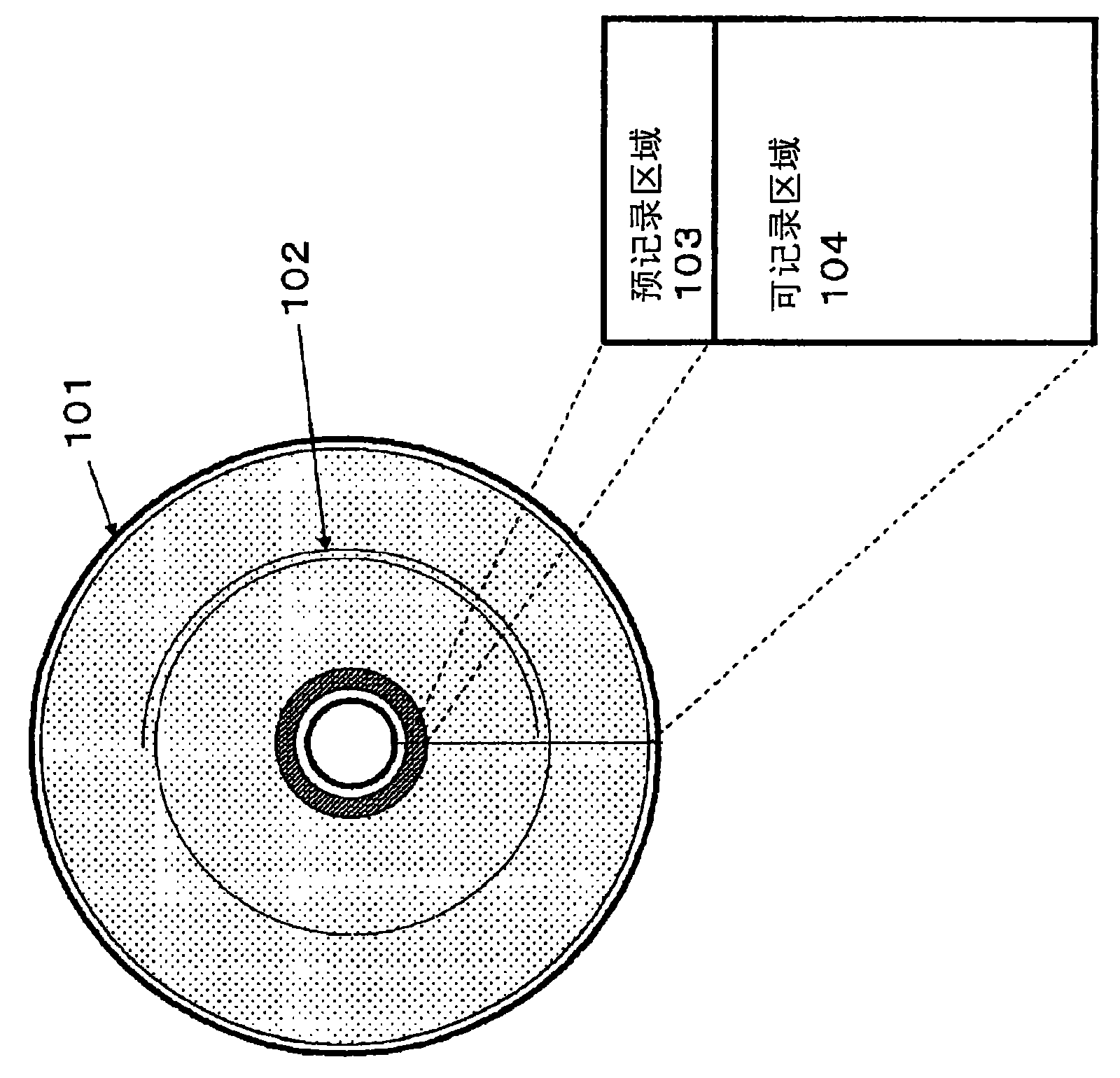
[0041] figure 1 The structure of the optical disc 101 according to the first embodiment of the present invention is shown, and especially the structure of the first information recording layer is shown.
[0042] On the optical disc 101, a plurality of tracks 102 are formed concentrically. Alternatively, a single track 102 may be formed in a spiral shape on the optical disc 101, or a plurality of tracks 102 may be formed in a spiral shape.
[0043] The area of the optical disc 101 includes a pre-recorded area 103 and a recordable area 104 .
[0044] Various parameters necessary for accessing the optical disc 101 are stored in the pre-recorded area 103 .
[0045] In the recordable area 104, recording learning and user data recording and reproduction are performed.
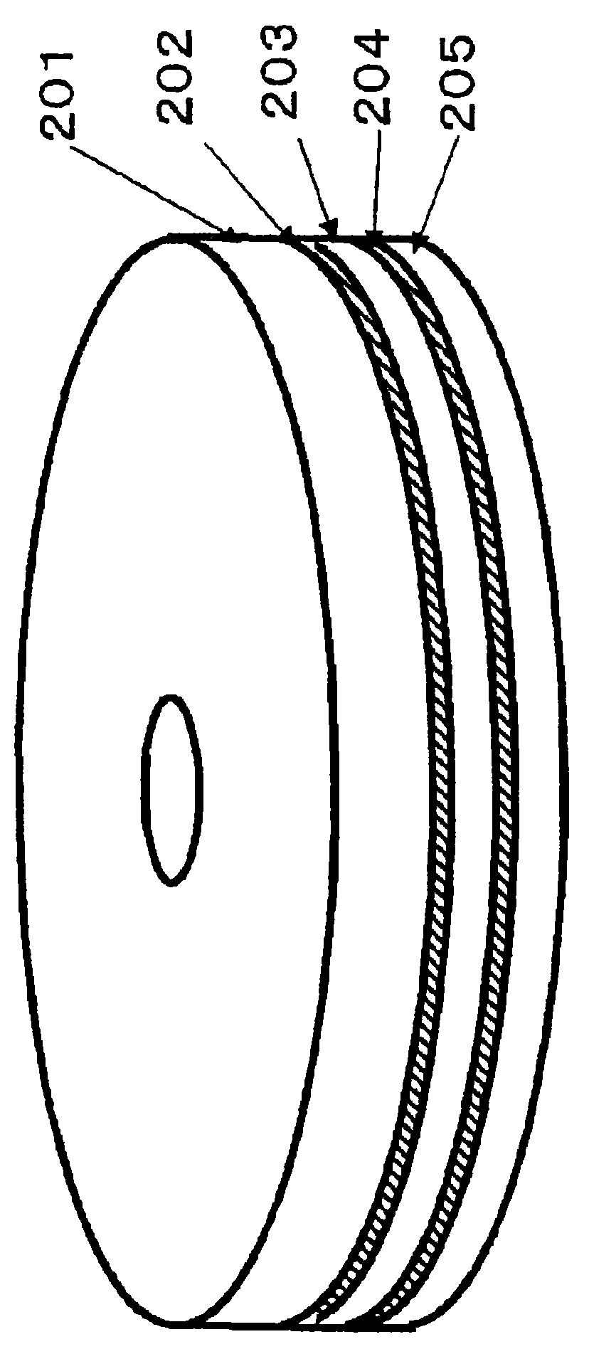
[0046] figure 2The structure of the single-sided two-layer optical disc of the present invention is shown.
[0047] exist figure 2 Among them, 201 is a substrate, 202 is a first information recording layer,...
Embodiment approach 2
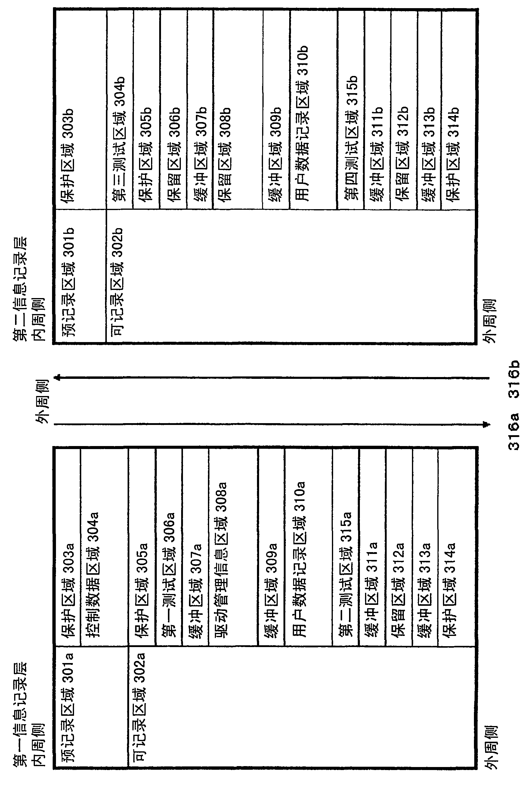
[0072] Figure 8 An arrangement diagram showing the radial positional relationship of the main parts of the optical disc area in another embodiment of the present invention.
[0073]In the figure, the upper part shows the protection area 503a of the first information recording layer, the control data area 504a, the protection area 505a, the first test area 506a, the buffer area 507a, the drive management information area 508a, the buffer area 509a, the user data recording area area 510a and second test area 515a. In the figure, the lower part shows the protected area 503b of the second information recording layer, the third test area 504b, the reserved area 505b, the protected area 506b, the reserved area 507b, the buffer area 508b, the reserved area 509b, the buffer area 510b, and the user data recording. area 511b and fourth test area 515b. Other structures and contents of each area are related to image 3 Since the two-layer optical disc of the illustrated embodiment 1 i...
Embodiment approach 3
[0087] use Figure 9 as well as Figure 10 , an optical disc device for recording with the optical disc described in the first or second embodiment will be described.
[0088] Figure 9 It is a block diagram showing the outline of the optical disc device 600 .
[0089] exist Figure 9 Among them, 601 is an optical disc. The optical disc 601 has the structure described in the first or second embodiment. Among them, the optical disc device 600 can record on an optical disc having a conventional structure, for example, a single-layer optical disc.
[0090] 602 is a semiconductor laser, 603 is a collimate lens, 604 is a beam splitter, 605 is a condensing mechanism, 606 is a condenser lens, 607 is a light detection mechanism, 608 is a reproduction signal calculation mechanism, and 609 is a focus control mechanism , 610 is a tracking control mechanism, 611 is an actuator, 612 is a controller, 613 is a laser driving mechanism, and 615 is a signal processing unit.
[0091] Here...
PUM
 Abstract
Description
Claims
Application Information
 - R&D Engineer
- R&D Manager
- IP Professional
- Industry Leading Data Capabilities
- Powerful AI technology
- Patent DNA Extraction
Browse by: Latest US Patents, China's latest patents, Technical Efficacy Thesaurus, Application Domain, Technology Topic, Popular Technical Reports.
© 2024 PatSnap. All rights reserved.Legal|Privacy policy|Modern Slavery Act Transparency Statement|Sitemap|About US| Contact US: help@patsnap.com


