
Novel electronic control carburetor electromagnetic valve

A solenoid valve, carburetor technology, applied in electrical control, engine control, fuel injection control, etc., can solve the problem of difficulty in identifying the normal operation and operation of the solenoid valve, inconvenient installation of LED indicators, and increased installation and manufacturing costs, etc. problems, to achieve the effect of reducing the emission of harmful gases and substances, reducing the volume and size, and saving fuel

Inactive Publication Date: 2009-11-04
温伟光
View PDF0 Cites 3 Cited by
  • Summary
  • Abstract
  • Description
  • Claims
  • Application Information

AI Technical Summary

Problems solved by technology

At present, the connection method of the solenoid valve originally prepared by the electronic control system device in the system and the internal structure and connection method of the solenoid valve are not ideal for how to facilitate large-scale production of this product, further improve reliability, and reduce noise. , and corresponding connection and fastening accessories are required during production and assembly, which increases installation and manufacturing costs
In addition, because the original solenoid valve of the control device is inconvenient to install LED indicators, it is not easy to visually identify whether the solenoid valve is working and running normally.

Method used


Image

  • Novel electronic control carburetor electromagnetic valve
  • Novel electronic control carburetor electromagnetic valve
  • Novel electronic control carburetor electromagnetic valve

Examples


Embodiment Construction

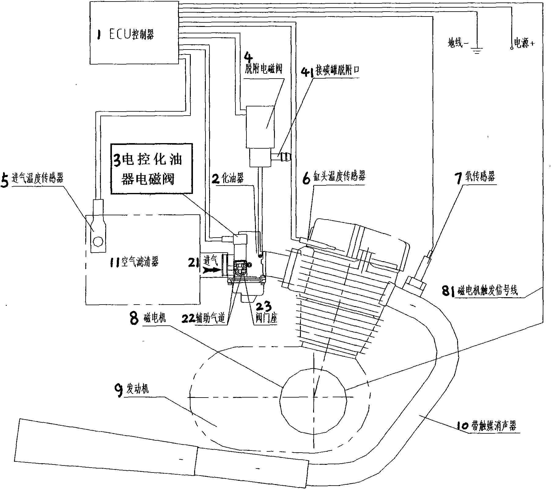
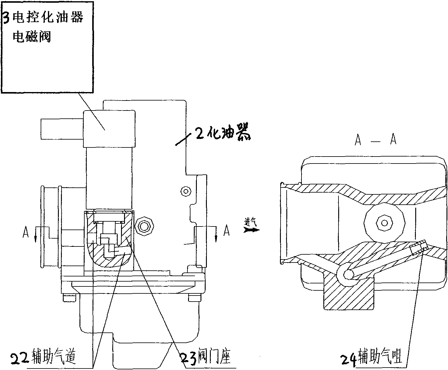
[0022] see figure 1 As shown in the schematic diagram of the carburetor electronically controlled integrated system, 1. The electronic controller (ECU) communicates with the electronically controlled carburetor solenoid valve 3, the desorption solenoid valve 4, the intake air temperature sensor 5, and the cylinder head temperature sensor 6 through signal lines. , the oxygen sensor 7 is connected; the magneto trigger signal line 81 is connected to the magneto 8 . The electronically controlled carburetor solenoid valve 3 is installed and fixed on the valve seat 23 of the carburetor 2 . The probe of the intake air temperature sensor 5 is installed on the air intake of the air cleaner 11 . The probe of cylinder head temperature sensor 6 is installed on the cylinder head position of engine 9 . The probe of oxygen sensor 7 is installed on the exhaust port of engine 9 .

[0023] see figure 2 As shown in the schematic diagram of the integration of the new carburetor and the elec...


PUM


Abstract

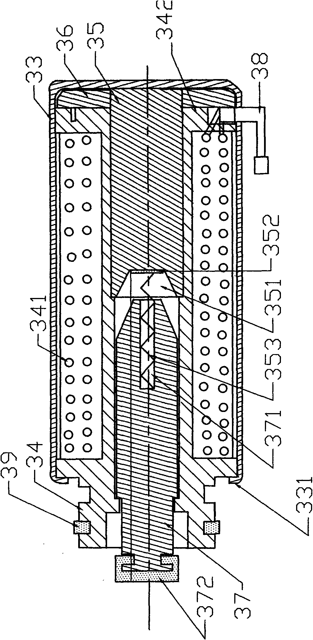
The invention provides a novel air flow control electromagnetic valve, namely, an electronic control carburetor electromagnetic valve, in a novel electronic control integral system of motor vehicle carburetor which can achieve the emission standard of Europe III. The outstanding feature of the electromagnetic valve is beautiful in appearance, remarkable shrinkage in size, convenient in mounting, high in sensitivity and fast in response speed, good in sealability, high in reliability; in addition the electromagnetic valve has obviously reduced working noise and has no general connection parts, and all the parts are connected by means of mutual embedding, welding and punching, and the electromagnetic valve is convenient to be added with an LED indicating lamp. The main parts of electromagnetic valve are: a drive coil and a frame (provided with a seal ring) thereof, a movable iron core and a seal ring thereof, a fixed iron core and a rubber gasket thereof, a soft iron shell, a soft iron gasket, a signal input wire, a resetting spring, a relevant connection wire and the like; if the LED indicating lamp is required to be mounted, a flexible circuit board, a patch light-emitting diode LED, a patch resistance and the like are further provided.

Description

technical field [0001] The invention relates to the technical field of an electronically controlled air supply system device for a motor vehicle engine, in particular to an airflow control solenoid valve with a new structure and connection method, which is suitable for indoor and outdoor applications. Background technique [0002] In the electronically controlled energy-saving purification system device (or electronic air supply system device) in automobiles and motorcycles, the air supply solenoid valve is the core executive component. Figure 5 In the block diagram of the working principle of the original electronic control air supply system device, the intake pipe of the valve seat of the air supply solenoid valve is connected to the air filter, the air outlet pipe is connected to the throttle between the carburetor and the engine, and the signal input line of the solenoid valve is connected to Controller ECU, the controller ECU in this system outputs a control signal to t...

Claims


Application Information

Patent Timeline
IPC IPC(8): F02M7/12F02D41/24
Inventor 温伟光
Owner 温伟光
Learn More