Light source driving device

A light source driving and light source module technology, applied in the direction of light sources, electric light sources, lighting devices, etc., can solve the problems of reducing the service life of components, accelerating component aging, high cost, etc., achieving stable current, prolonging the life of lamp tubes, and reducing the aging rate. Effect

Inactive Publication Date: 2009-10-28
HONG FU JIN PRECISION IND (SHENZHEN) CO LTD +1
View PDF0 Cites 9 Cited by
  • Summary
  • Abstract
  • Description
  • Claims
  • Application Information

AI Technical Summary

Problems solved by technology

However, this control method usually makes the components of the DC / AC conversion circuit 111 in a frequent switching state for a long time, which easily causes the components to become hot, accelerates the aging of the components, and reduces the service life of the components.
Moreover, a lamp current feedback circuit needs to be provided in the device, which takes up circuit space and is expensive

Method used


Image

  • Light source driving device
  • Light source driving device
  • Light source driving device

Examples


Embodiment Construction

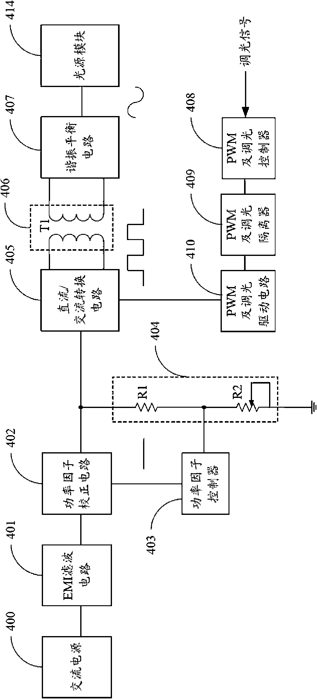
[0016] figure 2 Shown is a block diagram of a light source driving device in an embodiment of the present invention. The light source driving device is used to drive the light source module 414, which includes an AC power supply 400, an Electro-Magnetic Interference (EMI) filter circuit 401, a power factor correction circuit 402, a power factor controller 403, and an adjustable voltage divider circuit 404 , a DC / AC conversion circuit 405 , a transformer circuit 406 , a resonant balance circuit 407 , a PWM and dimming controller 408 , a PWM and dimming isolator 409 , and a PWM and dimming driving circuit 410 . In this embodiment, the light source module 414 includes a plurality of light sources—lamp tubes.

[0017] The AC power supply 400 provides an AC signal, which is filtered by the EMI filter circuit 401 and sent to the power factor correction circuit 402 . The EMI filter circuit 401 is connected between the AC power source 400 and the power factor correction circuit 402...


PUM


Abstract

The invention discloses a light source driving device, which is used for driving a light source module and comprises a power factor correction circuit, a DC / AC conversion circuit, a variable voltage circuit, a resonance balance circuit, a PWM and dimming controller, an adjustable voltage division circuit and a power factor controller, wherein the DC / AC conversion circuit is connected with output of the power factor correction circuit; the variable voltage circuit is connected with the DC / AC conversion circuit; the resonance balance circuit is connected with the variable voltage circuit; the PWM and dimming controller is connected with the DC / AC conversion circuit and used for outputting a control signal according to a received dimming signal, and the operation cycle of the control signal is a fixed value; the adjustable voltage division circuit is connected between the output of the power factor correction circuit and the ground; and the power factor controller is used for feeding signals after voltage division of the adjustable voltage division circuit back to the power factor correction circuit. The light source driving device can reduce the aging rate of the DC / AC conversion circuit and compensate the deviation of initial elements of the light source driving device.

Description

technical field [0001] The invention relates to a light source driving device, in particular to a light source driving device integrating an AC / DC converter. Background technique [0002] Generally, cold cathode fluorescent lamps (Cold Cathode Fluorescent Lamps, CCFLs) or external electrode fluorescent lamps (External Electrode Fluorescent Lamps, EEFLs) are used as backlight sources for LCD modules of flat panel display devices, such as liquid crystal displays and plasma display panels. In the LCD module, the duty cycle (duty cycle) output by the PWM (Pulse-width Modulator, pulse width modulation) controller is usually adjusted through the feedback current of the lamp tube, thereby adjusting the current flowing through the lamp tube. [0003] figure 1 Shown is an existing light source driving device for driving a light source module 14, which includes an AC power supply 10, an AC / DC converter 11, an inverter circuit 12, a PWM and dimming controller 13, and a PWM and dimming...

Claims


Application Information

Patent Timeline
IPC IPC(8): H05B41/295G05F1/70
Inventor 葛炽昌
Owner HONG FU JIN PRECISION IND (SHENZHEN) CO LTD
Why Eureka
Try Eureka