
Method and device for measuring electric hysteresis loop and strain loop of ferroelectric material simultaneously

A technology of hysteresis loops and ferroelectric materials, applied in measuring devices, measuring electrical variables, electromagnetic measuring devices, etc., can solve the problems of many accessories, inconvenient use, long measurement time, etc., and achieve the effect of high measurement accuracy

Inactive Publication Date: 2009-10-28
TSINGHUA UNIV
View PDF0 Cites 9 Cited by
  • Summary
  • Abstract
  • Description
  • Claims
  • Application Information

AI Technical Summary

Problems solved by technology

However, there are few strain loop test instruments in China at present, and there is no system for synchronous testing of the two
Moreover, the existing commercial hysteresis loop measurement system (Radiant Company of the United States and aixACT Company of Germany) provides many accessories, long measurement time and inconvenient use.

Method used


Image

  • Method and device for measuring electric hysteresis loop and strain loop of ferroelectric material simultaneously
  • Method and device for measuring electric hysteresis loop and strain loop of ferroelectric material simultaneously
  • Method and device for measuring electric hysteresis loop and strain loop of ferroelectric material simultaneously

Examples


Embodiment 1

[0041] The test sample uses PZT-5 (Institute of Acoustics, Chinese Academy of Sciences) ceramic sample, sample thickness d=1mm, electrode area S=0.7854cm 2 , the experiment uses a triangular wave with a frequency of 0.2Hz and 2 cycles as the measurement signal. During operation, lower the LVDT so that the probe is in contact with the surface of the sample electrode. Observe the input signal display waveform on the interface, and confirm that the LVDT signal Displacement (green waveform) is within the linear range.

[0042] Click the Start button on the interface to start the measurement. After the end, the hysteresis loop and strain loop of the second cycle are obtained. The interface displays the values ​​of spontaneous polarization Ps, remanent polarization Pr, and coercive field Ec at the same time. The data Files and loop diagrams are automatically saved with user name, sample name, test field strength and other parameters as file names. Measurement results from Figure...

Embodiment 2

[0052] The test sample uses PZT-5 (Institute of Acoustics, Chinese Academy of Sciences) ceramic sample, sample thickness d=1mm, electrode area S=0.7854cm 2 , the experiment uses a frequency of 0.2Hz, 2 cycles of the triangular wave as the polarization field strength. Before measurement, click the Polarization Centering and Strain Centering buttons on the interface to perform automatic zero compensation on the loop, and click the Strain Filter button on the interface to filter the strain loop. Figure 7 It is the measurement result after compensating the electric hysteresis loop and strain loop by computer. The interface shows Ps=33.9219μC / cm2, Pr=31.554μC / cm2, Ec=1.11417kV / mm, and draws two loops and test signals in real time (such as Figure 7 a. Figure 7 shown in b).


PUM


Abstract

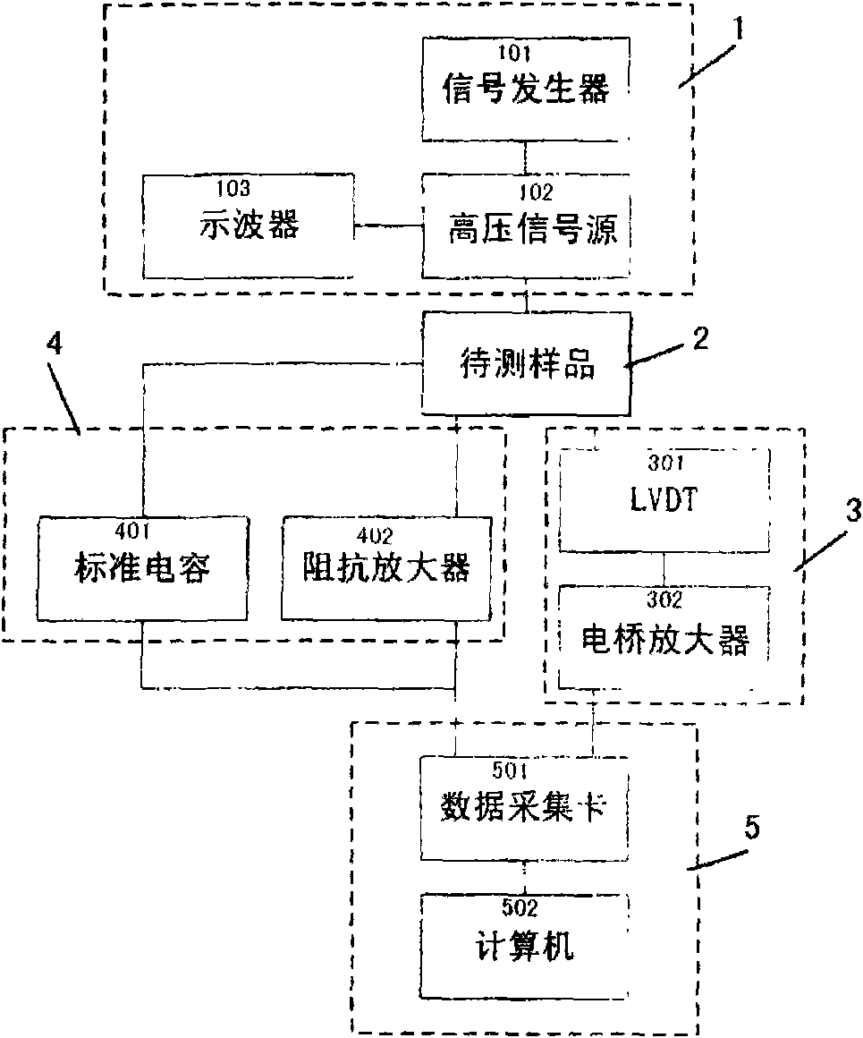
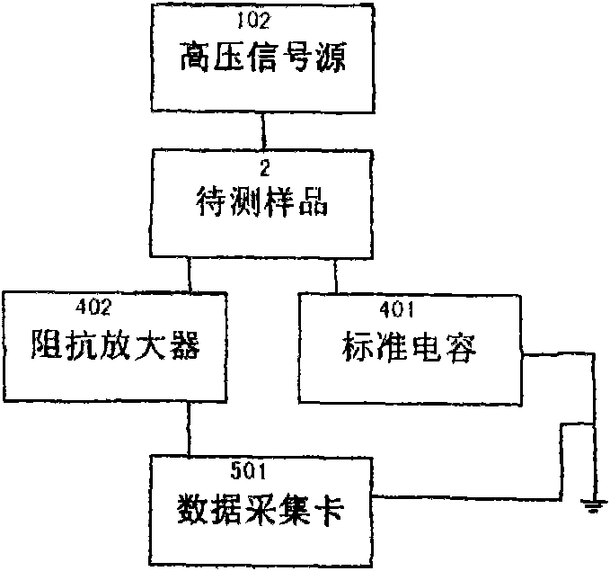
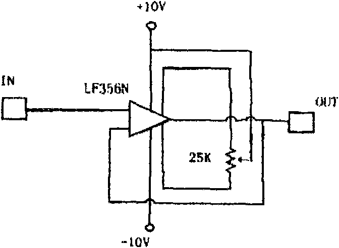
The invention discloses a method and a device for measuring an electric hysteresis loop and a strain loop of a ferroelectric material simultaneously; the measurement device comprises four parts: test signal output, electric hysteresis loop test, strain loop test and equipment control and data collecting treatment; waveform signals generated by a signal generator are amplified by a high voltage amplifier and are subsequently applied in a series loop consisting of a sample to be measured and a standard capacitor; the voltage signals at two ends of the standard capacitor are input to a collecting card by an impedance amplifier; simultaneously, the strain signal detected by an LVDT displacement sensor is input to a data collecting card; and the electric hysteresis loop and the strain loop are obtained by a computer. The method and the device solve the problem of no instruments for measuring the electric hysteresis loop and the strain loop simultaneously in the currently national ferroelectric piezoelectric material research. The method and the device have stable test data, high efficiency and good self-definition and extensibility and can greatly save the test time. The technical proposal has simple structural principle and is easy, convenient and practical for preparing and assembling devices.

Description

technical field [0001] The invention belongs to the technical field of testing ferroelectric and piezoelectric materials, in particular to a method and a device for simultaneously measuring hysteresis loops and strain loops of ferroelectric materials. Background technique [0002] Ferroelectric and piezoelectric materials have high electromechanical conversion efficiency and good performance controllability, so they have been widely used in electronic technology, from the small ignition system of automobiles to the control of aerospace adaptive wings, from tiny From motors to MEMS, ferroelectric materials are inseparable. The important feature of the constitutive relation of ferroelectric materials is the hysteresis loop. This includes not only hysteresis loops (polarization-electric field loops), but also strain loops (strain-electric field loops), also known as butterfly loops (Butterfly Loop). In order to better study the electromechanical coupling characteristics of fe...

Claims


Application Information

Patent Timeline
Patent Type & Authority Applications(China)
IPC IPC(8): G01R31/00G01R19/25G01B7/16
Inventor 张勇李继威黄春林邓长生戴遐明
Owner TSINGHUA UNIV
Learn More