
Sintered soaking plate and manufacturing method thereof

A manufacturing method and technology of soaking plate, which are applied in indirect heat exchangers, lighting and heating equipment, etc., can solve the problems of excessive contact thermal resistance between the capillary structure and the inner surface of the shell, obstruction of steam flow in the support structure, and high machining costs. , to achieve the effect of being conducive to effective diffusion, solving the increasing heat flux density, and convenient production

Active Publication Date: 2013-01-30
ZHONGSHAN WEIQIANG TECH
View PDF0 Cites 2 Cited by
  • Summary
  • Abstract
  • Description
  • Claims
  • Application Information

AI Technical Summary

Problems solved by technology

The machining cost of this heat pipe vapor chamber is high, it is not easy to weld, and it is easy to deform
Therefore, as the requirements for vapor chambers become higher and higher, bottlenecks appear in various types of vapor chambers, such as insufficient capillary force, excessive contact thermal resistance between the capillary structure and the inner surface of the shell, and support structures for steam The obstruction of flow and the insufficient strength of the vapor chamber directly affect the heat dissipation efficiency

Method used


Image

  • Sintered soaking plate and manufacturing method thereof
  • Sintered soaking plate and manufacturing method thereof
  • Sintered soaking plate and manufacturing method thereof

Examples


Embodiment Construction

[0040] The present invention will be described in further detail below in conjunction with the accompanying drawings and specific embodiments, but not as a limitation of the present invention.

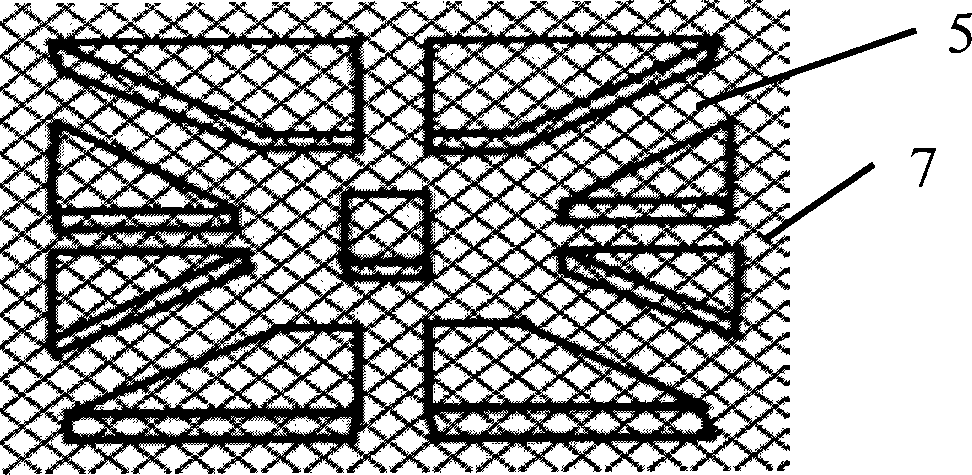
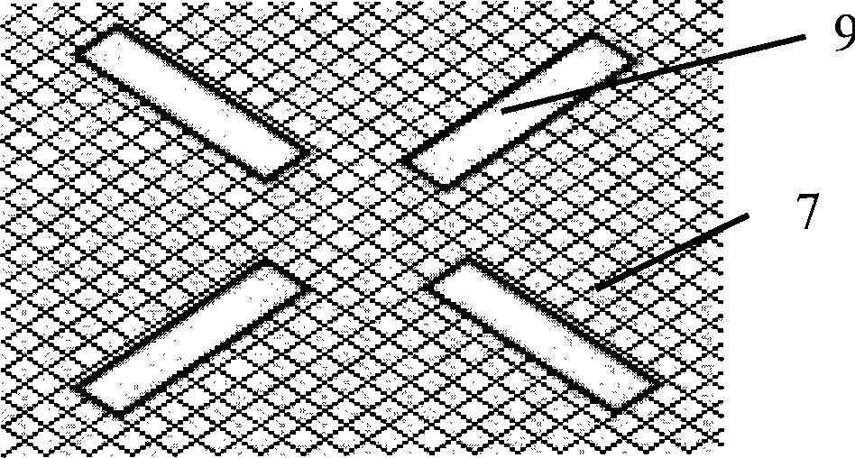
[0041] like figure 1 The shown sintered vapor chamber includes a flattened airtight casing 1 , a porous capillary structure 2 , a stamped supporting structure 3 and a working fluid filled in the airtight casing 1 . The porous capillary structure 2 is formed by sintering metal powder on the inner wall of the airtight casing 1, and the metal powder is copper powder, aluminum powder, nickel powder or nano-carbon powder. The support structure 3 is placed in the airtight casing 1, and the protruding part of the support structure 3 is in contact with the inner wall of the airtight casing 1 to support the airtight casing 1. The material of the airtight casing 1 is elastic 1. A metal material with high thermal conductivity can be copper, copper alloy, aluminum, aluminum alloy or stainless ste...


PUM


Abstract

The invention discloses a sintered soaking plate which comprises a closed casing, a capillary structure, a supporting stricture and working fluid, wherein the closed casing is formed in such a way that a metal circular pipe is flattened and both ends of the metal circular pipe are closed; the capillary structure is sintered on the internal wall of the closed casing; the supporting structure is formed by stamping wire meshes; the working fluid is filled in the closed casing; and the supporting structure is arranged in the hollow cavity of the closed casing. The invention also discloses the manufacturing method of the sintered soaking plate. The capillary structure of the soaking plate has small thermal contact resistance with the internal surface of the closed casing and strong capillary force, thereby being convenient for the working fluid to flow back to an evaporating surface. The supporting structure is formed by directly stamping the wire meshes and manufactured conveniently, the mesh screens of the wire meshes and stamped grooves are used as channels where steam flows, and the channels are beneficial to the effective diffusion of the steam and also used as return channels of the working fluid. The soaking plate has simple structure and can be especially applied to the heat-dissipating design of large-scale servers.

Description

technical field [0001] The invention relates to a vapor soaking plate and a manufacturing method thereof, in particular to a sintered soaking heat soaking plate and a manufacturing method thereof. Background technique [0002] With the continuous development of electronic technology, the operating frequency of electronic components is getting higher and higher, and the heat flux generated is also increasing. Electronic heat dissipation technology has also been highly valued by the industry. Electronic heat dissipation has the following significant trends: local heat flux density is high, heat flux distribution is uneven, high heat flux is confined to a small space, and so-called hot spots are prone to occur, and electronic equipment is prone to instantaneous power surges during the startup process, but The total heat that needs to be dissipated is not very large (estimated not to exceed 500W). [0003] In order to solve the above problems, different types of vapor chambers ...

Claims


Application Information

Patent Timeline
Patent Type & Authority Patents(China)
IPC IPC(8): F28D15/02B22F3/11
CPCF28D15/046F28D15/0233
Inventor 陈其亮谢远东高媛媛古巧殊
Owner ZHONGSHAN WEIQIANG TECH
Learn More