
Illumination utensil

一种照明器具、灯具的技术,应用在阅读灯领域,能够解决一般产品没有适切结构、不便等问题,达到操作性长期良好、散热性好、防止咬磨的效果

Inactive Publication Date: 2009-10-21
TOSHIBA LIGHTING & TECH CORP +1
View PDF1 Cites 2 Cited by
  • Summary
  • Abstract
  • Description
  • Claims
  • Application Information

AI Technical Summary

Problems solved by technology

[0009] It can be seen that the above-mentioned existing lighting fixtures obviously still have inconvenience and defects in structure and use, and need to be further improved urgently
In order to solve the above-mentioned problems, the relevant manufacturers have tried their best to find a solution, but for a long time no suitable design has been developed, and the general product has no suitable structure to solve the above-mentioned problems. This is obviously the relevant industry. Urgent problem

Method used


Image

  • Illumination utensil
  • Illumination utensil
  • Illumination utensil

Examples


Embodiment Construction

[0063] In order to further explain the technical means and effects of the present invention to achieve the intended purpose of the invention, the specific implementation, structure, features and effects of the lighting fixture proposed according to the present invention will be described in detail below in conjunction with the accompanying drawings and preferred embodiments. The description is as follows.

[0064] The aforementioned and other technical contents, features and effects of the present invention will be clearly presented in the following detailed description of preferred embodiments with reference to the drawings. Through the description of the specific implementation mode, when the technical means and functions adopted by the present invention to achieve the predetermined purpose can be obtained a deeper and more specific understanding, but the accompanying drawings are only for reference and description, and are not used to explain the present invention be restri...


PUM


Abstract

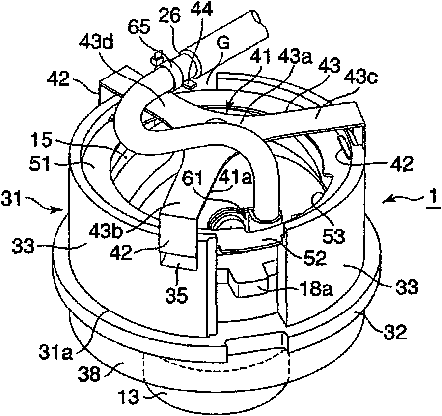
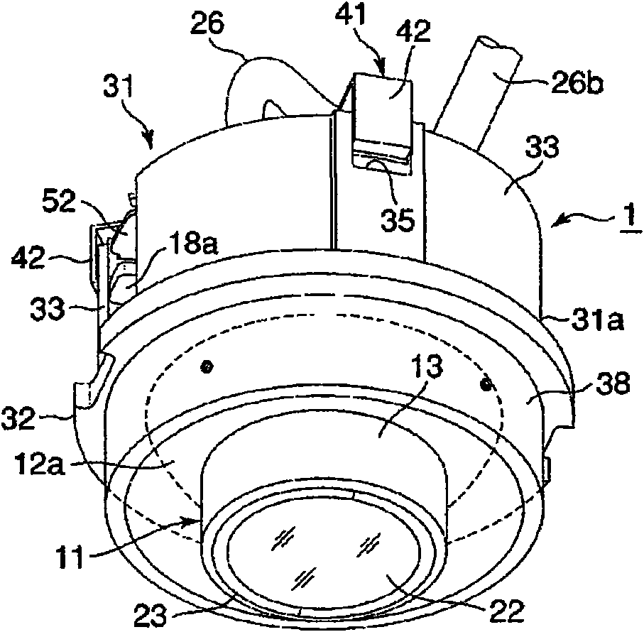
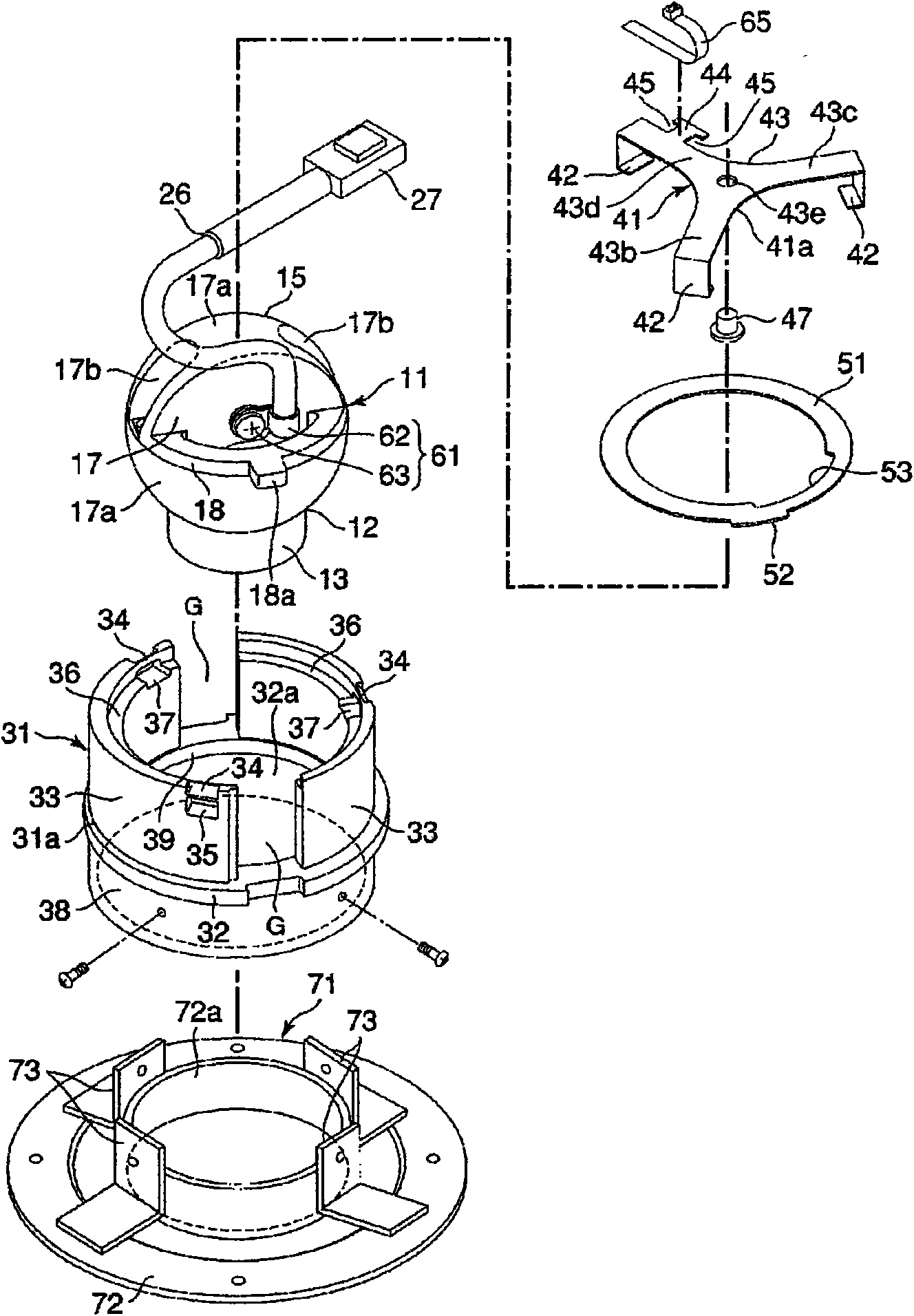
The present invention relates to an illumination utensil, having a good radiating character and capable of maintaining an operation of altering a lamp direction for a long time. A reading lamp (1) is provided with a lamp (11) with a built-in light source (20), an utensil body (31) and a plate spring (41). The lamp (11) has a cover (12) and a lamp main body (15). The cover (12) has an external surface (12a) composed of part of a sphere. The lamp main body (15) is made of metal, and has a back face (17a) composed of part of the sphere. The utensil body (31) has a slide guide part (39) with a receiving external surface (12a). the slide guide part (39) supports the lamp (11) rotatably so as to alter an light irradiation direction of the lamp (11). By means of pressing the back face (17a) of the lamp (11) by the plate spring (41), the lamp (11) is mounted in the utensil body (31). One of the slide guide part (39) of the utensil body (31) and the cover (12) of the lamp (11) is made of metal, the other is made of resin.

Description

technical field [0001] The present invention relates to a lighting appliance, in particular to a lighting appliance capable of changing the irradiation direction of light, such as a reading light installed near seats of transportation vehicles such as trains, airplanes, and ships. Background technique [0002] Conventionally, as such a lighting fixture, for example, a downlight (downkight) capable of changing the irradiation direction of light by rotatably holding a lamp having a roughly spherical shape in a roughly cylindrical fixture body (for example, , with reference to Japanese Patent Application Laid-Open No. 2005-149790). When assembling this downlight, the lamp is placed on the edge of a circular opening formed by partially narrowing the inner circumference of the fixture body, and a leaf spring is attached from the back side of the lamp to press the lamp against the opening. the edge of. [0003] With this configuration, the luminaire is held stationary by the fri...

Claims


Application Information

Patent Timeline
Patent Type & Authority Applications(China)
IPC IPC(8): F21V21/30F21V21/14F21S8/10
CPCB60Q3/0253B64D2011/0053B60Q3/44
Inventor 小野桂辅
Owner TOSHIBA LIGHTING & TECH CORP
Learn More