Air flow detection circuit of digital air flow meter

An air flow meter and air flow technology, applied in the direction of measuring flow/mass flow, liquid/fluid solid measurement, measuring devices, etc., can solve the problem that the engine performance is greatly affected and cannot accurately reflect the instantaneous change of engine air intake , Signal output value accuracy is not high, etc.

Active Publication Date: 2009-10-07
ZHEJIANG HENKO AUTO SPARE PARTS
View PDF0 Cites 10 Cited by
  • Summary
  • Abstract
  • Description
  • Claims
  • Application Information

AI Technical Summary

Problems solved by technology

[0009] The above-mentioned thermal air flowmeter uses the measurement method of constant flow mass flow, and the air flow is detected by a simple Wheatstone bridge circuit, temperature compensation circuit and proportional amplification circuit. The accuracy of the signal output value is not high, and it cannot be accurately measured. It reflects the instantaneous change of the intake air volume of the engine, which has a great influence on the working performance of the engine

Method used


Image

  • Air flow detection circuit of digital air flow meter
  • Air flow detection circuit of digital air flow meter
  • Air flow detection circuit of digital air flow meter

Examples


Embodiment Construction

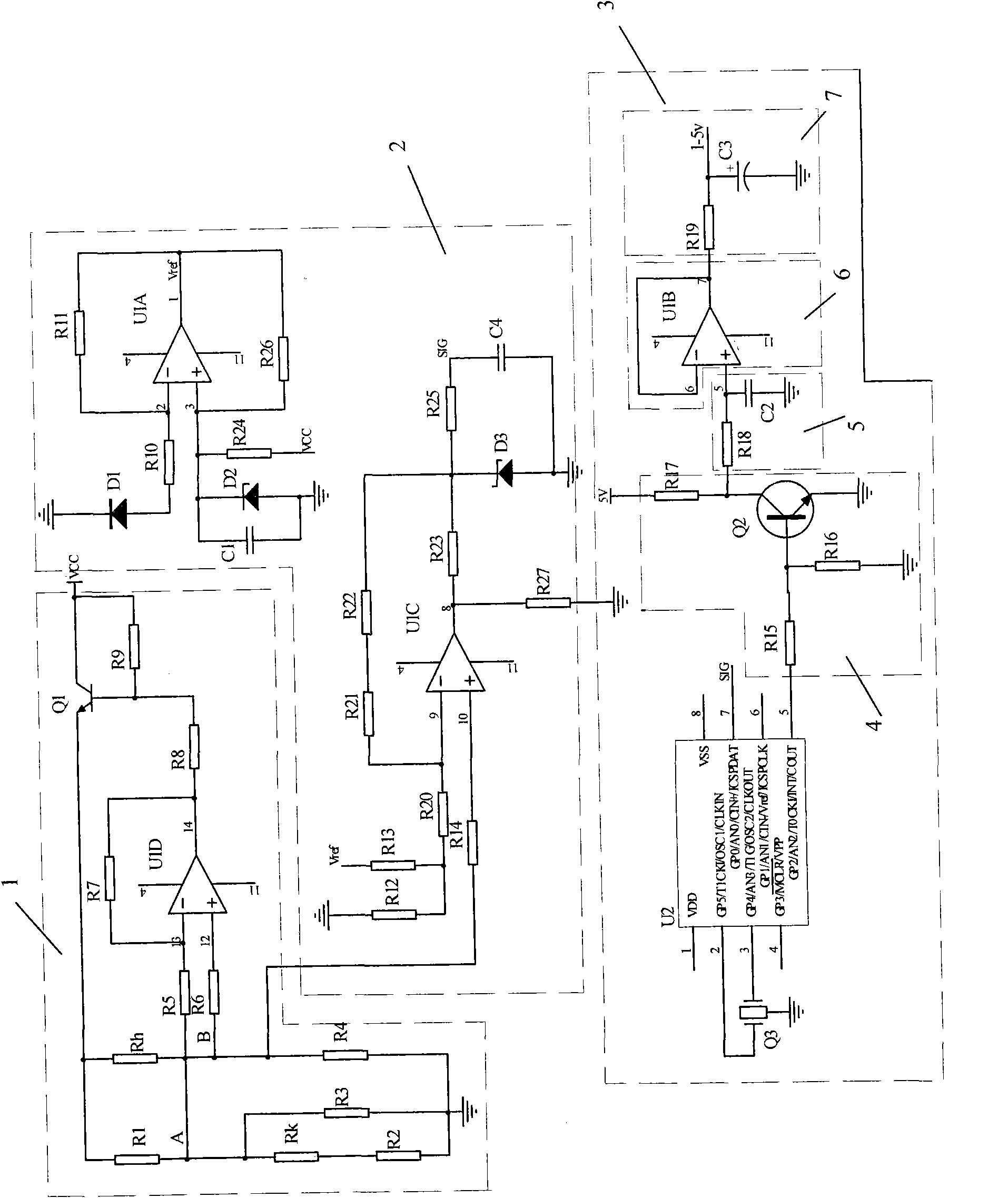
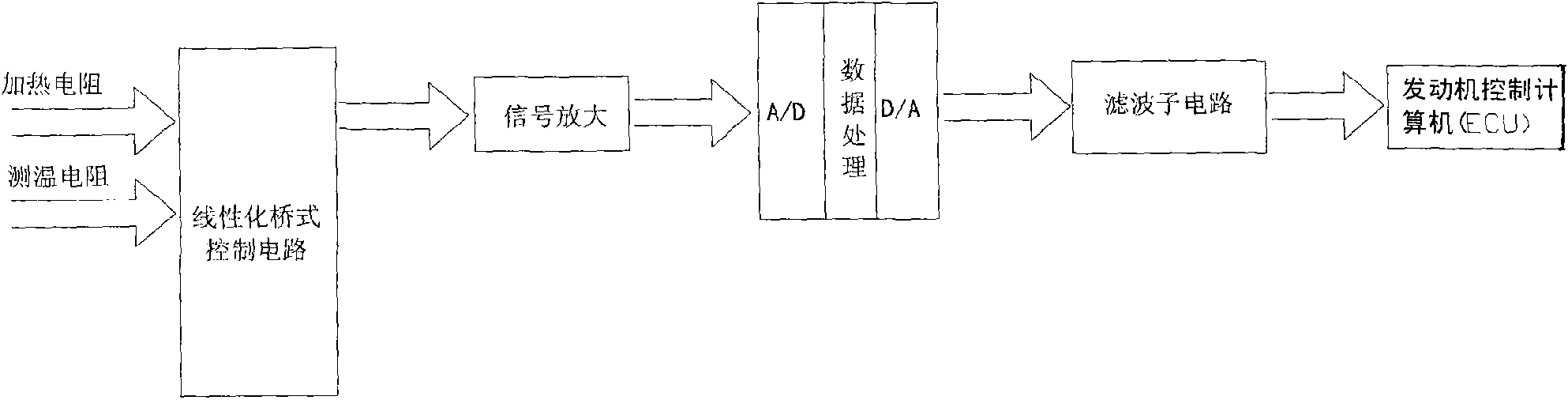
[0019] refer to figure 1 , figure 2 It can be seen that the air flow detection circuit of the digital air flow meter of the present invention includes a bridge sub-circuit 1 and a proportional amplification sub-circuit 2 electrically connected to each other, and the bridge sub-circuit 1 is a linearized bridge sub-circuit, wherein the speed measurement Resistor R4 is a thin film strain gauge, and temperature measuring resistor RK is a negative coefficient thermistor. The temperature measuring resistor RK is connected in series with resistor R2, and then the temperature measuring resistor RK, resistor R2 and resistor R3 are connected in parallel; the proportional amplification sub-circuit 2 It is also electrically connected to the data processing and filtering sub-circuit 3 .

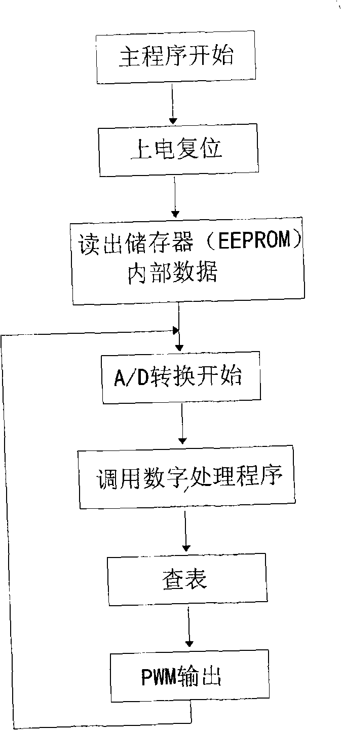
[0020] refer to figure 1 , figure 2 , image 3 , described data processing and filter sub-circuit 3 are made up of single-chip microcomputer U2 (its model: pic12f683) and crystal oscillator Q3, swit...


PUM


Abstract

The invention disclose an air flow detection circuit of digital air flow meter, wherein the bridge branched circuit (1) is a linearization bridge branched circuit, wherein a speed measurement resistance R4 is the film strain gauge and a temperature measurement resistance RK is a negative coefficient thermistor and the temperature measurement PK is in series connection with the resistance R2 and then the temperature measurement resistance RK is in parallel connection with the resistance R2 and R3; the linear amplification branched circuit (2) is electrically connected with a data treatment and filter branched circuit (3) and the data treatment and filter branched circuit converses the air flow signal output by the linear amplification branched circuit into the digital signal and the ideal output value is obtained by a program and the output of the digital signal by controlling the duty ratio of the pulse width modulation, finally the analog quantity obtained by a low pass filtering sub-circuit is output and sent to a motor control computer. Therefore the air flow into the electric eruption motor in flash is accurately and rightly measured. The air flow detection circuit has features of automatic convenient operation, quick signal transfer speed and high working efficiency.

Description

1. Technical field [0001] The invention relates to an air flow meter for automobiles, in particular to an air flow detection circuit of the automobile air flow meter. 2. Background technology [0002] The air flow meter is installed on the air intake passage between the gasoline filter and the throttle valve of the car, and is used to measure the air flow inhaled into the engine, and its output signal is used as the main parameter for controlling the fuel injection quantity in the fuel electronic injection system of the car engine , determines the basic fuel injection quantity of the car. In order to obtain the best fuel-concentration mixture of EFI engine under various operating conditions, it is necessary to correctly and accurately measure the air flow inhaled into the EFI engine at every moment, as an electronic control unit to calculate and control the fuel injection quantity main basis. [0003] At present, the known air flowmeters are mainly hot-wire and hot-film. T...

Claims


Application Information

Patent Timeline
Patent Type & Authority Applications(China)
IPC IPC(8): G01F1/698F02D41/18
Inventor 陈锦翔唐厚君
Owner ZHEJIANG HENKO AUTO SPARE PARTS
Why Eureka
Try Eureka