
LED bulb

A technology for LED bulbs and lamp sockets, which is applied in the layout of electric lamp circuits, lighting and heating equipment, semiconductor devices of light-emitting elements, etc. compact effect

Inactive Publication Date: 2011-03-23
ZHEJIANG GUANTONG TECH DEV
View PDF0 Cites 1 Cited by
  • Summary
  • Abstract
  • Description
  • Claims
  • Application Information

AI Technical Summary

Problems solved by technology

But it has some disadvantages at the same time: since multiple LEDs are arranged on a horizontal mounting board, the range of LED light-emitting viewing angles is 110 degrees to 130 degrees, so when one or several LEDs in the LED bulb light up, it will make the LEDs A certain area around the lampshade of the bulb forms a blind area of ​​brightness, especially the lower area around the outside of the LED lampshade, which affects the lighting effect of the LED bulb

Method used


Image

  • LED bulb
  • LED bulb
  • LED bulb

Examples


Embodiment 1

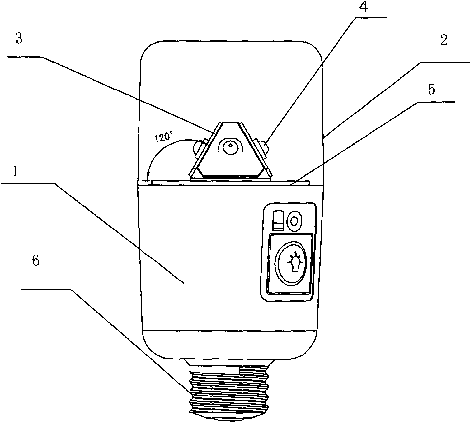
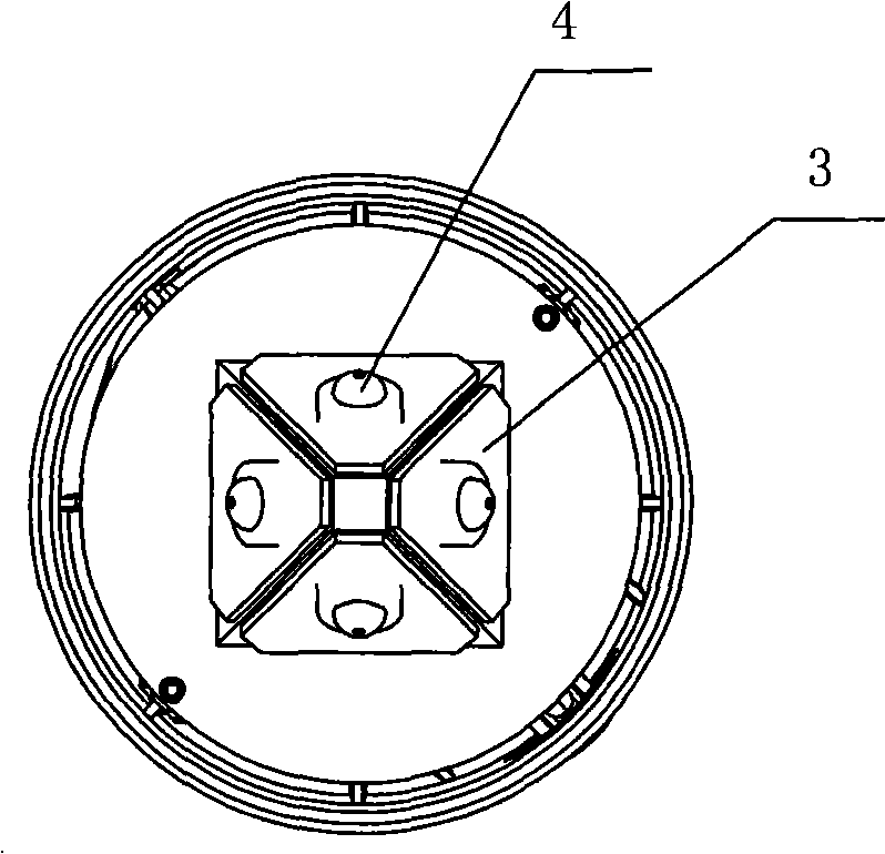
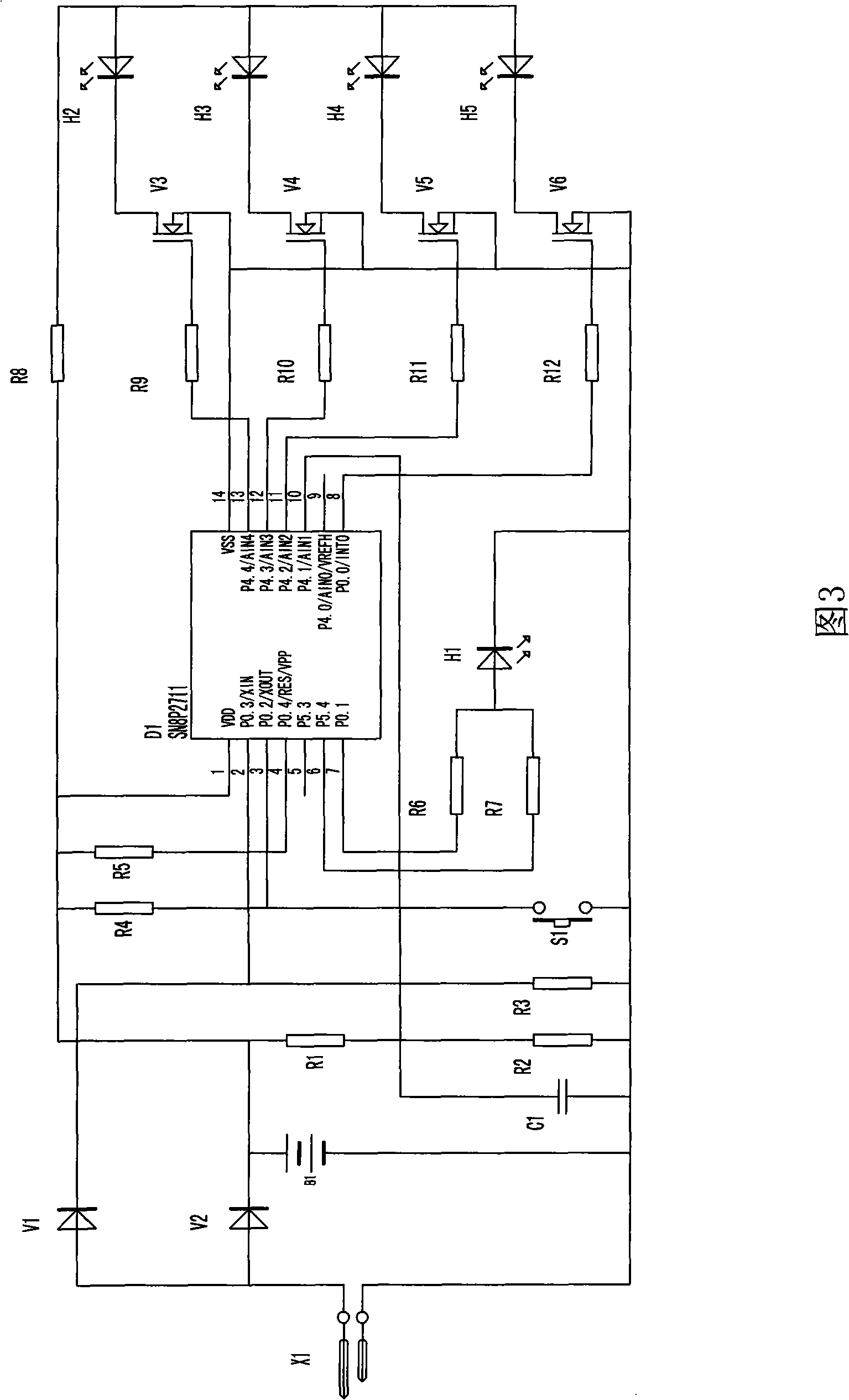
[0020] Embodiment 1: An LED bulb includes a lamp holder 1, a lampshade 2 arranged on the lamp holder 1, and a driving circuit. The lamp holder 1 is provided with four LED chassis 3, and the four LED chassis 3 enclose a four Pyramid, each LED base frame 3 is provided with LED 4, the angle between the LED base frame 3 and the horizontal plane is 120 degrees, the driving circuit includes a control circuit that makes the four LEDs light up cyclically, and the control circuit includes model SN8P2711 The single-chip microcomputer and the switch control circuit of the single-chip microcomputer have four signal output terminals, and the four signal output terminals respectively correspond to its thirteenth pin, twelfth pin, eleventh pin and eighth pin. The single-chip microcomputer is electrically connected to the four LEDs through the switch control circuit. The single-chip microcomputer sends out pulse signals to each signal output terminal in turn, and the pulse signal from the singl...

Embodiment 2

[0023] The second embodiment: the other parts are the same as the first embodiment, and the difference is that the angle formed by the LED chassis 3 and the horizontal plane is 125 degrees or 140 degrees. The duration of the pulse signal sent by the microcontroller to each signal output terminal is 1 millisecond.

Embodiment 3

[0024] The third embodiment: the other parts are the same as the first embodiment, and the difference is that the number of LEDs is three LEDs, and the three LED chassis 3 form a triangular pyramid. The duration of the pulse signal sent by the microcontroller to each signal output terminal is 2 milliseconds.

[0025] The working time of each LED during a cycle of lighting is determined according to the number of LEDs in the LED bulb, and the cycle time of multiple LEDs is controlled within 10 milliseconds.


PUM


Abstract

The invention discloses a LED bulb, which comprises a lamp socket, and a lampshade and a drive circuit disposed on the lamp socket; at least three LED under-frames enclosing into a pyramid are disposed on the lamp socket; a LED is disposed on each LED under-frame which has a included angle of 120-140 degrees between the horizontal plane. The control circuit comprises a single chip microcomputer and an on / of control circuit; the single chip microcomputer is in electric connection with at least three LEDs by the on / of control circuit; the single chip microcomputer sends pulse signals with duration of 0.5-2 millisecond to every signal output terminal successively and circularly. The advantages of the invention comprises: it causes the working of a plurality of LEDs to consume the electric quantity of one LED, can fully guarantee that no brightness blind area exists in the 360 degrees range around the lampshade; at the same time, eliminates the brightness blind area under the lampshade periphery.

Description

Technical field [0001] The invention relates to a light bulb, in particular to an LED light bulb. Background technique [0002] LED bulbs have the advantages of environmental protection, low power consumption and long service life, which are the main directions for vigorous promotion of lighting lamps in the future. There is a structure of an LED bulb including a lamp holder, a plastic lampshade, an LED light source array and a control circuit. The LED light source array is arranged in the plastic lampshade. The light source array is arranged on a horizontal mounting board by a plurality of LEDs arranged in concentric circles. The number is determined according to the needs of lighting brightness, and the control circuit controls all LEDs to work or turn off at the same time. Although the brightness of the lighting is better when all the LEDs in the LED bulb are working, in some cases where the brightness of the lighting is not high, it will be more expensive to light up the LED...

Claims


Application Information

Patent Timeline
Patent Type & Authority Patents(China)
IPC IPC(8): F21Y101/02F21S2/00F21V23/00H05B37/02F21V19/00F21K9/232F21K9/238F21Y115/10
Inventor 蔡林
Owner ZHEJIANG GUANTONG TECH DEV
Learn More