Vehicle side mirror

A technology for reversing mirrors and vehicles, which is applied to vehicle parts, optical observation devices, transportation and packaging, etc. It can solve the problems of incomplete identification of dead-end areas, illusions caused by drivers, accidental traffic accidents, etc., to achieve easy identification, prevent illusions, The effect of low manufacturing cost

Active Publication Date: 2009-09-23
董志良
View PDF0 Cites 0 Cited by
  • Summary
  • Abstract
  • Description
  • Claims
  • Application Information

AI Technical Summary

Problems solved by technology

[0005] However, although the above-mentioned reversing mirror can slightly expand the driver's field of vision, it cannot fully identify the blind spot. In particular, there is still the problem that the light of the headlights of the vehicle coming from the rear is directly reflected into the driver's eyes, and accidents may still occur. traffic accident
Moreover, it is quite difficult to manufacture the complex of the plane mirror and the convex mirror, and it will also give drivers an illusion. The separate products of the plane mirror and the convex mirror are because more than two mirror surfaces will be produced, so the cost will be increased, and the driver will have to observe the two mirrors at the same time. a mirror, thus causing problems such as driver fatigue

Method used


Image

  • Vehicle side mirror
  • Vehicle side mirror
  • Vehicle side mirror

Examples


Embodiment 1

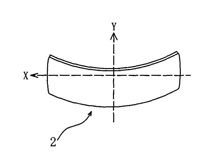
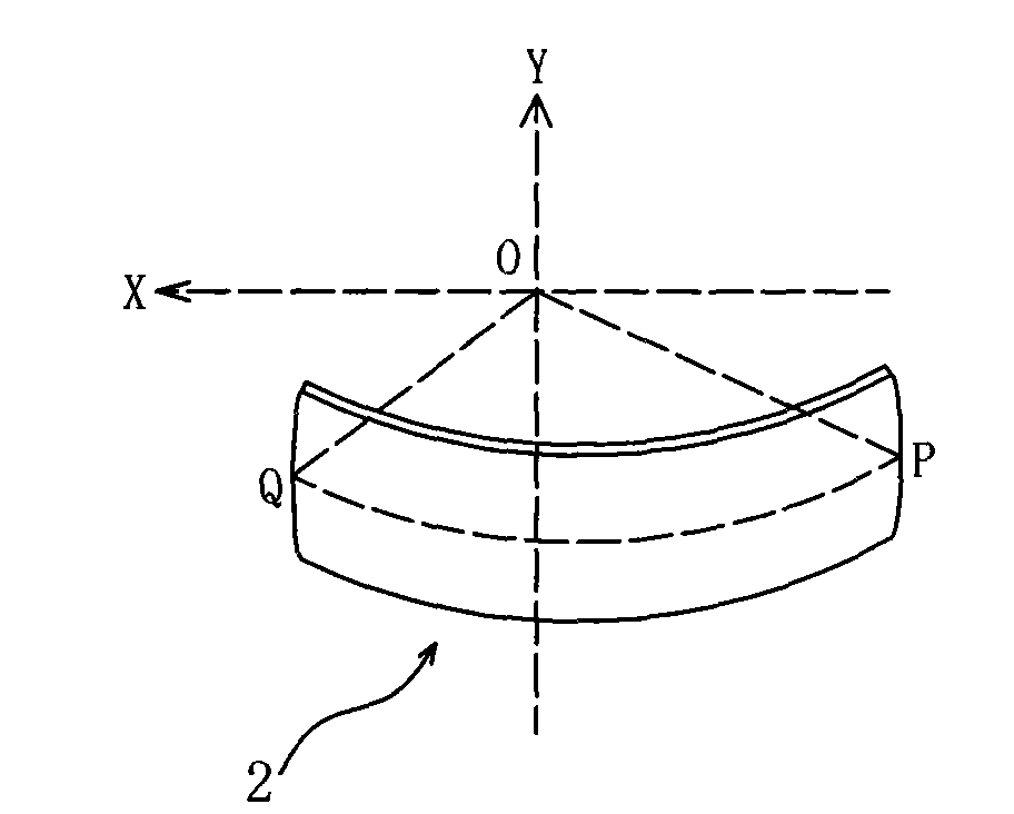
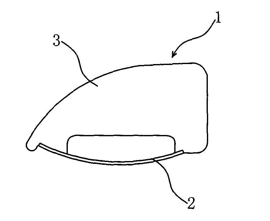
[0020] Example 1: see figure 2 , 3 , The vehicle mirror 1 described in this embodiment is suitable to be installed outside the vehicle body on one side of the cab, and includes a housing 3 and a lens 2 installed in the housing. The housing 3 is mounted on the mirror base of the vehicle body When up, it can rotate relative to the body. The contribution of the present invention is characterized in that the lens 2 is an aspherical convex lens with a one-piece structure. The structure of the lens can be understood as follows: the direction of the lens from the side of the vehicle body to the outside of the vehicle is regarded as the length direction of the lens, namely figure 1 As shown in the X axis direction, the Y axis direction is the width direction of the lens. If the lens is cut along the Y axis, the width direction of the lens, the longitudinal section of the lens can be regarded as a circular arc. The curvature of the arc of the initial longitudinal section is 0.2, (it can ...

Embodiment 2

[0022] Example 2: see Figure 4 , 5 The vehicle mirror 1'described in this embodiment is suitable for being installed outside the vehicle body on the side of the passenger cabin, and it also includes a housing and a lens installed in the housing, and the housing is mounted on the vehicle’s mirror base When up, it can rotate relative to the body. The structure of the lens and the method of forming the lens in this embodiment are the same as those in the embodiment, except that the curvature of the arc of the lens from the vehicle body side to the outer longitudinal section of the vehicle is gradually increased from 0.2 to 1.2.

[0023] If you look at the left and right side mirrors from the driver’s position, the lenses on both sides of the body should have different curvatures due to the distance and angle from the mirror 1'. For the mirror 1', if it is on the side of the body If the curvature of the longitudinal section of the lens is less than 0.2, the light from the headlights ...


PUM


Abstract

The invention discloses a vehicle side mirror comprising a side mirror shell rotatably connected with the vehicle body and a lens arranged in the shell. The lens is an aspherical convex mirror of integral structure. All the vertical sections of the lens can be regarded as a section of circular arc. The lens is formed by smooth connection of a plurality of circular arcs with gradually increasing curvature and the same center of circle from the vehicle body side to the vehicle outside. A curve formed by the connection of the middle points of the plurality of the circular arcs is on the same plane as the center of circle. The side mirrors at left side and right side are aspherical convex mirrors with concave single structure, which are formed with optimal curvature, can not only enlarge the field of vision of drivers, but also faciliate the indentification of dead zones and prevent accidents caused by the direct reflection of the headlight of a vehicle traveling behind to eyes. Besides, the side mirror is easy in manufacturing and low in manufacturing cost and can also prevent the phenomenon of eyestrain caused by the illusion of drivers.

Description

Technical field: [0001] The present invention relates to a rear-view mirror for a vehicle, which is a non-curved convex mirror with a single structure that is strictly and delicately formed with an optimal curvature. Through this mirror, the driver can maintain the best vision, can easily identify the blind area, and at the same time Avoid direct reflection of the light from the headlights of vehicles moving from behind to the driver’s eyes. Background technique: [0002] In order to enable drivers to observe the rear of the vehicle, mirrors are generally installed on both sides of the front of the vehicle. That is, the driver's cab and the passenger's cab side. The mirror surface of the reversing mirror first used a flat surface that was easy to make. Later, a convex mirror surface was used to broaden the field of vision. At present, two methods are used. One is to install a small round convex mirror on the original mirror surface, and the other is a mirror surface. It is cut in...

Claims


Application Information

Patent Timeline
Patent Type & Authority Applications(China)
IPC IPC(8): B60R1/06
Inventor 张成董志良
Owner 董志良
Why Eureka
Try Eureka