Non-overlapping clock-generating circuit with independently regulated two-phase pulse duration
A clock generation circuit and independent adjustment technology, applied in the field of microelectronics and solid-state electronics, can solve the problems related to pulse width and non-overlapping time
- Summary
- Abstract
- Description
- Claims
- Application Information
AI Technical Summary
Problems solved by technology
Method used
Image
Examples
Embodiment Construction
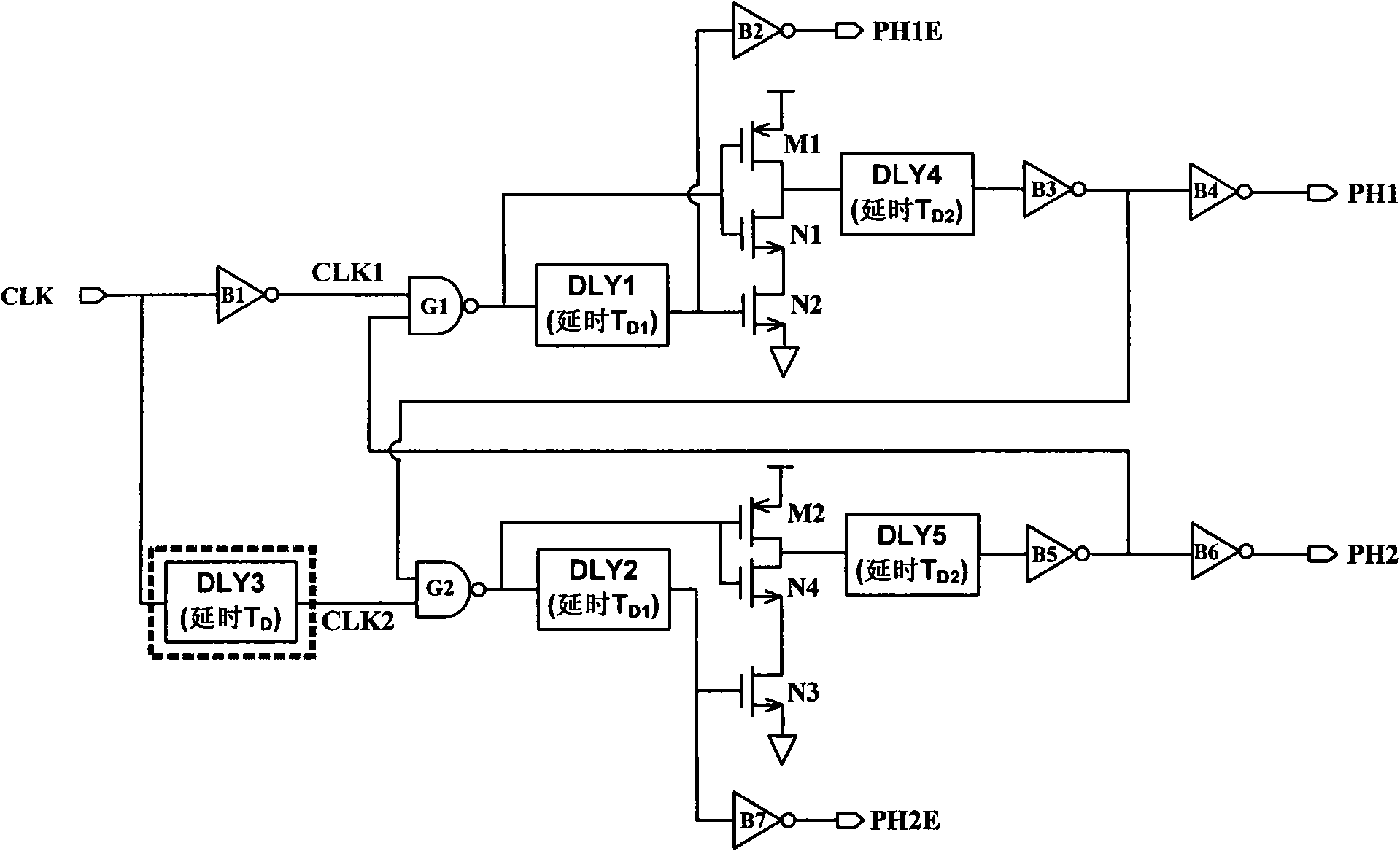
[0037] Technical solution of the present invention refers to figure 1 . figure 1 It is a structural diagram of a non-overlapping clock generation circuit that independently adjusts two-phase pulse widths.
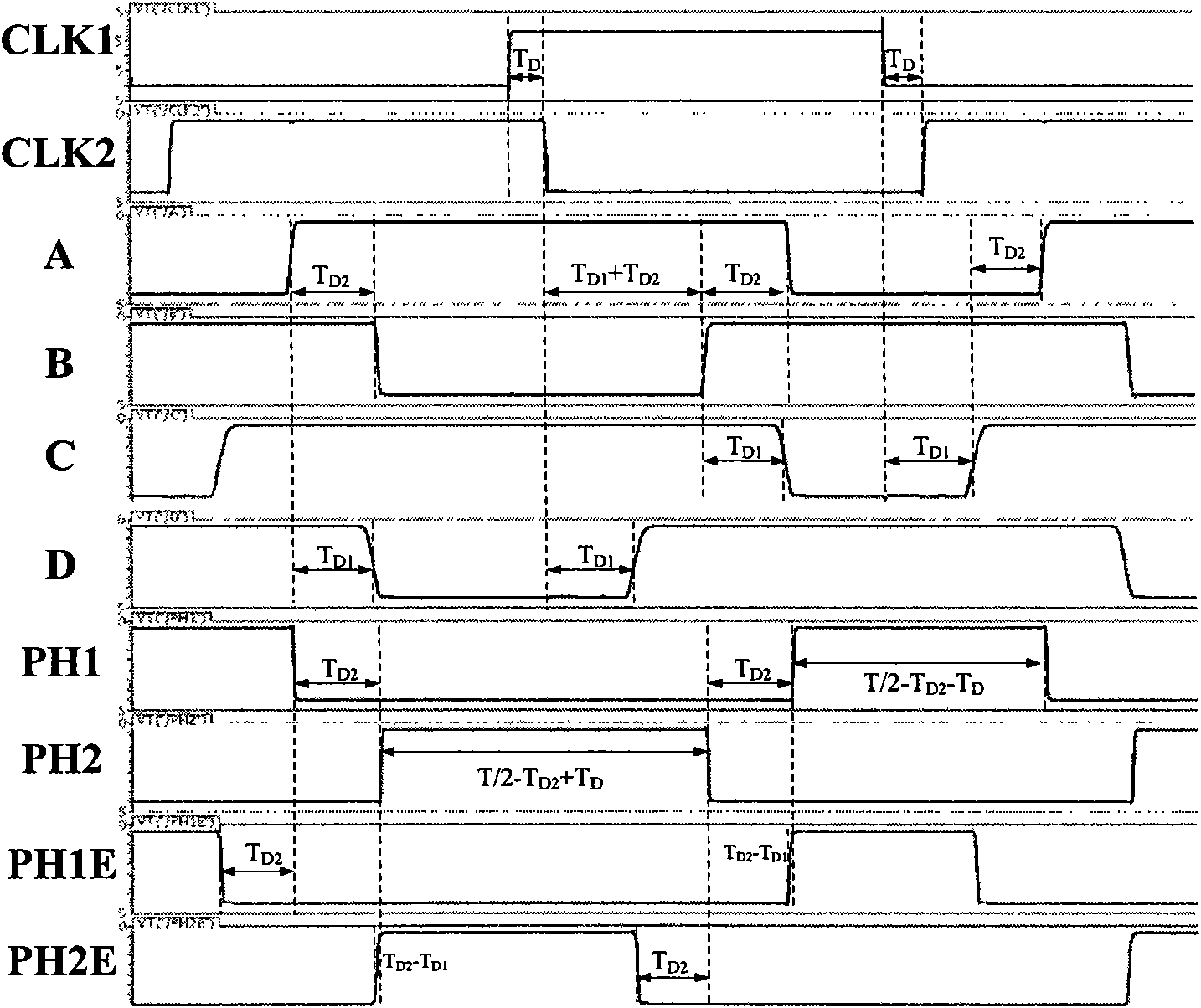
[0038] When the delay parameter T D D1 +T D2 , the timing is as figure 2 shown.
[0039] The pulse width of the clock PH1 phase is: T / 2-T D2 -T D .
[0040]The pulse width of the clock PH2 phase is: T / 2-T D2 +T D .
[0041] Two-phase non-overlapping clock PH1 phase and PH2 phase non-overlapping time is: T D2 .
[0042] Clock PH1E rising edge arrival time - PH1 rising edge arrival time = T D1 -T D2 .
[0043] Clock PH2E rising edge arrival time - PH2 rising edge arrival time = T D1 -T D2 .
[0044] The falling edge of clock PH1E comes before the falling edge of PH1 to T D2 .
[0045] The falling edge of clock PH2E comes before the falling edge of PH2 to T D2 .
[0046] where T is the clock period with a 50% duty cycle of the input.
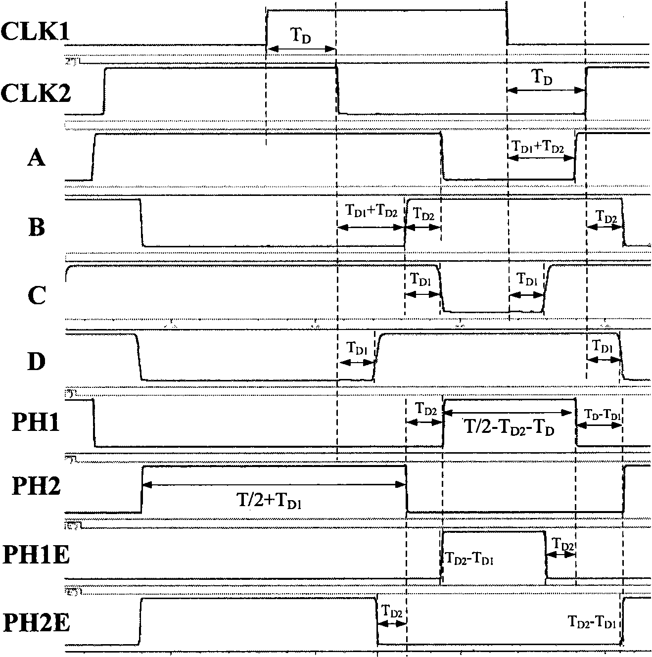
[0047] When T D...
PUM
 Abstract
Description
Claims
Application Information
 - R&D
- Intellectual Property
- Life Sciences
- Materials
- Tech Scout
- Unparalleled Data Quality
- Higher Quality Content
- 60% Fewer Hallucinations
Browse by: Latest US Patents, China's latest patents, Technical Efficacy Thesaurus, Application Domain, Technology Topic, Popular Technical Reports.
© 2025 PatSnap. All rights reserved.Legal|Privacy policy|Modern Slavery Act Transparency Statement|Sitemap|About US| Contact US: help@patsnap.com


