
Non-overlapping clock-generating circuit with independently regulated two-phase pulse duration

A clock generation circuit and independent adjustment technology, applied in the field of microelectronics and solid-state electronics, can solve the problems related to pulse width and non-overlapping time

Inactive Publication Date: 2009-09-16
TSINGHUA UNIV
View PDF0 Cites 24 Cited by
  • Summary
  • Abstract
  • Description
  • Claims
  • Application Information

AI Technical Summary

Problems solved by technology

But its disadvantage is also that the pulse width is related to the non-overlapping time

Method used


Image

  • Non-overlapping clock-generating circuit with independently regulated two-phase pulse duration
  • Non-overlapping clock-generating circuit with independently regulated two-phase pulse duration
  • Non-overlapping clock-generating circuit with independently regulated two-phase pulse duration

Examples


Embodiment Construction

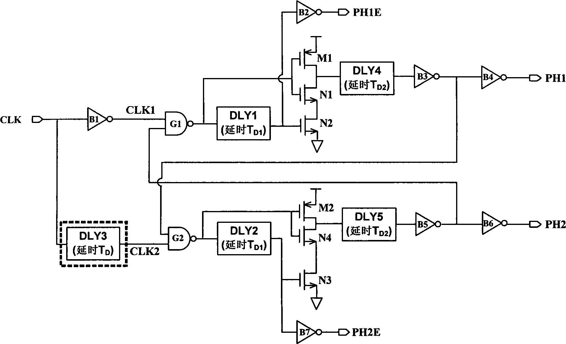
[0037] Technical solution of the present invention refers to figure 1 . figure 1 It is a structural diagram of a non-overlapping clock generation circuit that independently adjusts two-phase pulse widths.

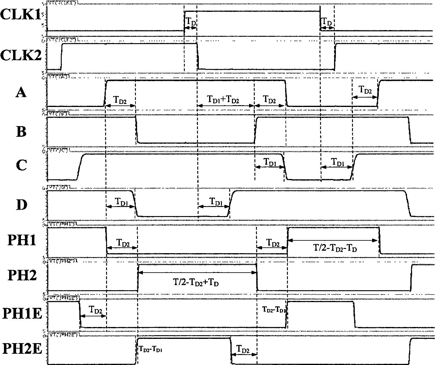
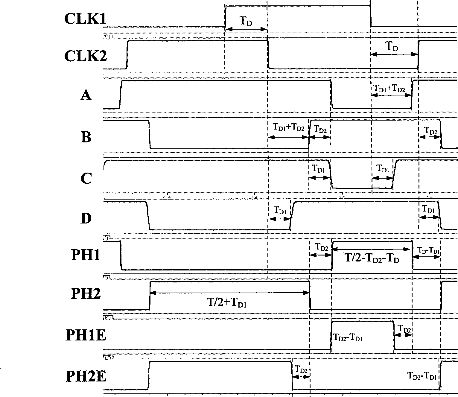
[0038] When the delay parameter T D D1 +T D2 , the timing is as figure 2 shown.

[0039] The pulse width of the clock PH1 phase is: T / 2-T D2 -T D .

[0040]The pulse width of the clock PH2 phase is: T / 2-T D2 +T D .

[0041] Two-phase non-overlapping clock PH1 phase and PH2 phase non-overlapping time is: T D2 .

[0042] Clock PH1E rising edge arrival time - PH1 rising edge arrival time = T D1 -T D2 .

[0043] Clock PH2E rising edge arrival time - PH2 rising edge arrival time = T D1 -T D2 .

[0044] The falling edge of clock PH1E comes before the falling edge of PH1 to T D2 .

[0045] The falling edge of clock PH2E comes before the falling edge of PH2 to T D2 .

[0046] where T is the clock period with a 50% duty cycle of the input.

[0047] When T D...


PUM


Abstract

The invention relates to a non-overlapping clock-generating circuit with independently regulated two-phase pulse duration, belonging to the field of non-overlapping clock-generating circuit. The circuit is characterized in that a time delay unit is provided in front of CLK2 of two-phase non-overlapping clock-generating circuit which can generate advance timing, the input of the time delay unit is connected with clock signals, the output thereof is connected with an input terminal CKL2 of an alternative denial gate; the time delay unit can be used to independently regulate the pulse duration of PH1 and PH2. When parameters meet the condition that TD is less than or equal to TD1+TD2, PH1 pulse duration of the clock is T / 2-TD2-TD, PH2 pulse duration of the clock is T / 2-TD2+TD; non-overlapping time between PH1 and PH2 is TD2; clock PH1E falls by TD2 earlier than PH1does, clock PH2E falls by TD2 earlier than PH2 does; when TD1 is equal to TD2, PH1E and PH1 can rise simultaneously, so do PH2E AND PH2. The circuit of the invention has the advantage that pulse duration, non-overlapping time and advance timing rising edge of the two-phase non-overlapping clock can be adjusted.

Description

technical field [0001] The invention belongs to the design of ultra-large-scale integrated circuits in the field of microelectronics and solid-state electronics, and relates to a new type of two-phase non-overlapping clock generation circuit, which can be widely used in ΔΣ modulators, pipeline A / D, filters and other switches Capacitor circuit design. Background technique [0002] The two-phase non-overlapping clock generation circuit is one of the important unit modules of the analog circuit, and is widely used in various switched capacitor circuits. The two-phase non-overlapping clock is used to control the on-off of the switch in the circuit, so that the node is not driven by two voltage sources at the same time. It also provides an early shutdown clock to reduce the impact of signal-related charge injection effects. [0003] In a switched capacitor circuit, the sampling capacitance is usually reduced step by step, and the load capacitance is not equal in the two-phase c...

Claims


Application Information

Patent Timeline
IPC IPC(8): H03K3/78H03K3/017H03K5/00
Inventor 李冬梅朱颖佳刘力源姜汉钧李福乐王志华
Owner TSINGHUA UNIV
Learn More