Eureka AIR delivers breakthrough ideas for toughest innovation challenges, trusted by R&D personnel around the world.

Optimal design method of superconducting magnet used for magnetic resonance imaging (MRI) device

A superconducting magnet, optimized design technology, applied in the direction of magnetic resonance measurement, etc., can solve the problems of exceeding the current carrying capacity of superconducting materials, local magnetic field is too strong, and the results are unreasonable

Inactive Publication Date: 2009-09-16
INST OF ELECTRICAL ENG CHINESE ACAD OF SCI
View PDF2 Cites 28 Cited by
  • Summary
  • Abstract
  • Description
  • Claims
  • Application Information

AI Technical Summary

Problems solved by technology

Although these methods have global optimization capabilities, since the optimization problem of the main magnet of magnetic resonance imaging (MRI) is a multi-objective, multi-parameter nonlinear optimization problem, the solution space is complex, and the direct use of random algorithms for coil parameter optimization has great potential. Large blindness reduces algorithm efficiency and even makes optimization difficult
However, in the short-cavity MRI magnet design of this invention, the current density used to directly design the coil will lead to unreasonable results. The current density at both ends of the designed coil is too large, and the local magnetic field is too strong, which often exceeds the current-carrying capacity of the superconducting material.

Method used


Image

  • Optimal design method of superconducting magnet used for magnetic resonance imaging (MRI) device
  • Optimal design method of superconducting magnet used for magnetic resonance imaging (MRI) device
  • Optimal design method of superconducting magnet used for magnetic resonance imaging (MRI) device

Examples


Embodiment Construction

[0077] The present invention will be further described below in conjunction with the drawings and specific embodiments.

[0078] The design method flow of an embodiment of the present invention is as follows:

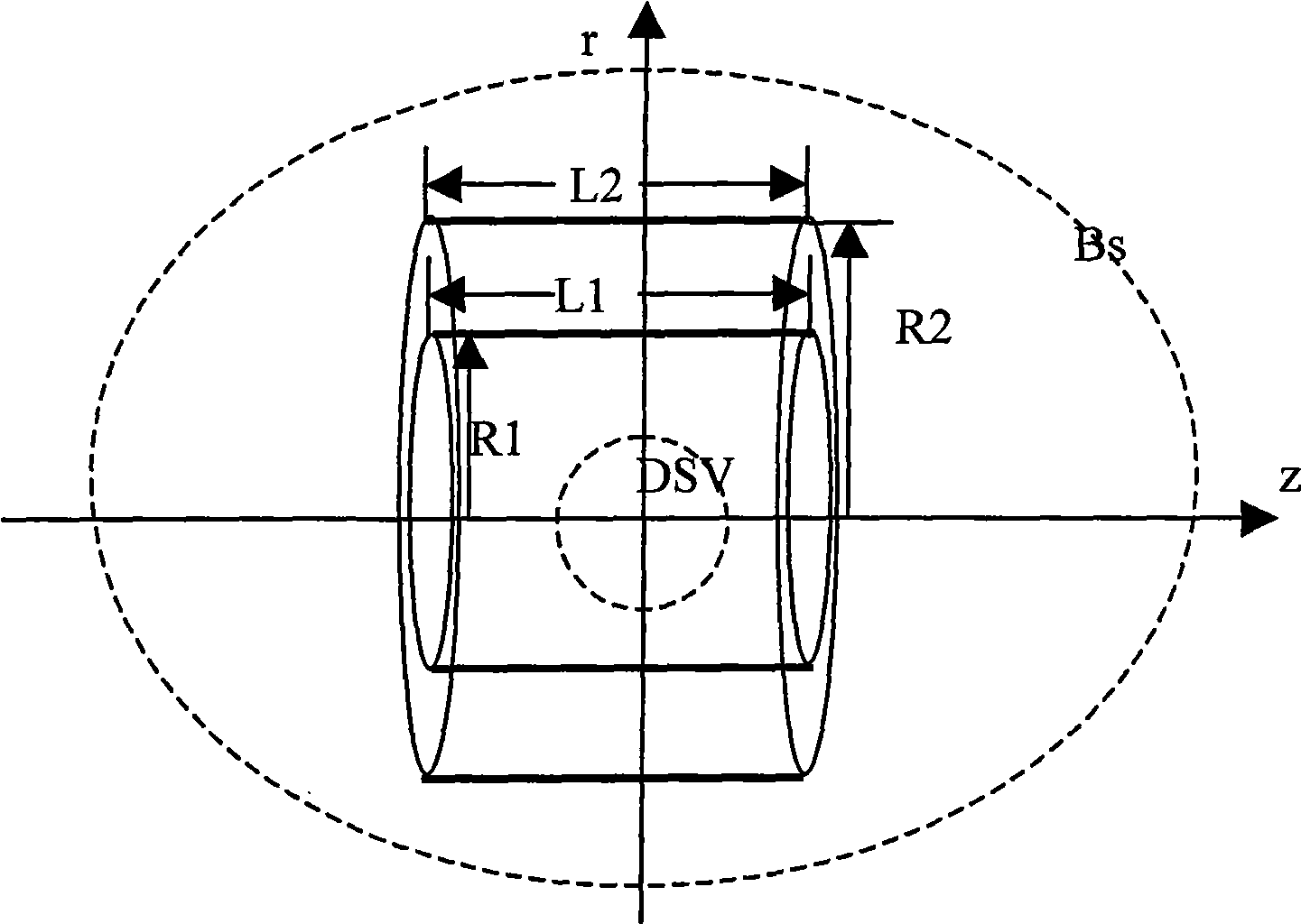
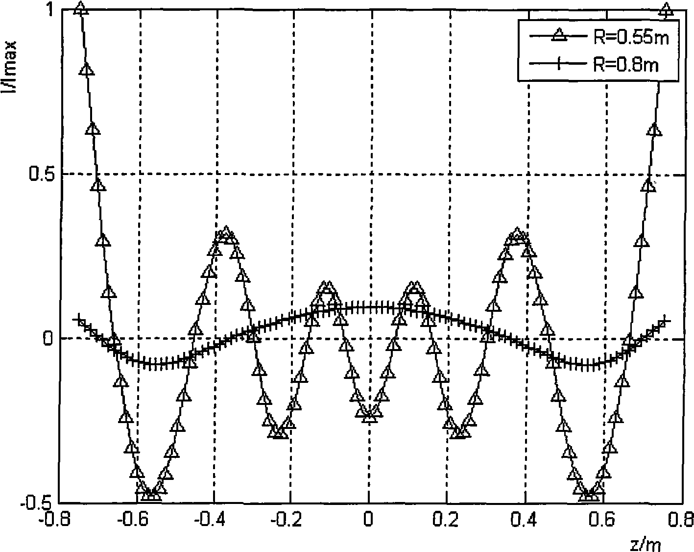
[0079] figure 1 Schematic diagram of the design area. The radius of the current layer of the main coil is R1 = 0.55m, and the radius of the current layer of the shielding coil is R2 = 0.8m. Length L 1 =L 2 =1.5m, the current of each layer is divided into n=100 parts. The central magnetic field is set to 1.0T, the target point is at radius Rdsv=0.225m, uniformity is 5ppm, and m=301 points are uniformly selected on the arc of θ from -5π / 6 to 5π / 6. On the semi-ellipse where the minor axis is 5m and the major axis is 6m, m=51 points are uniformly selected on the semi-ellipse with θ from -π / 6 to π / 6, and the stray magnetic field is taken as B s = 5G.

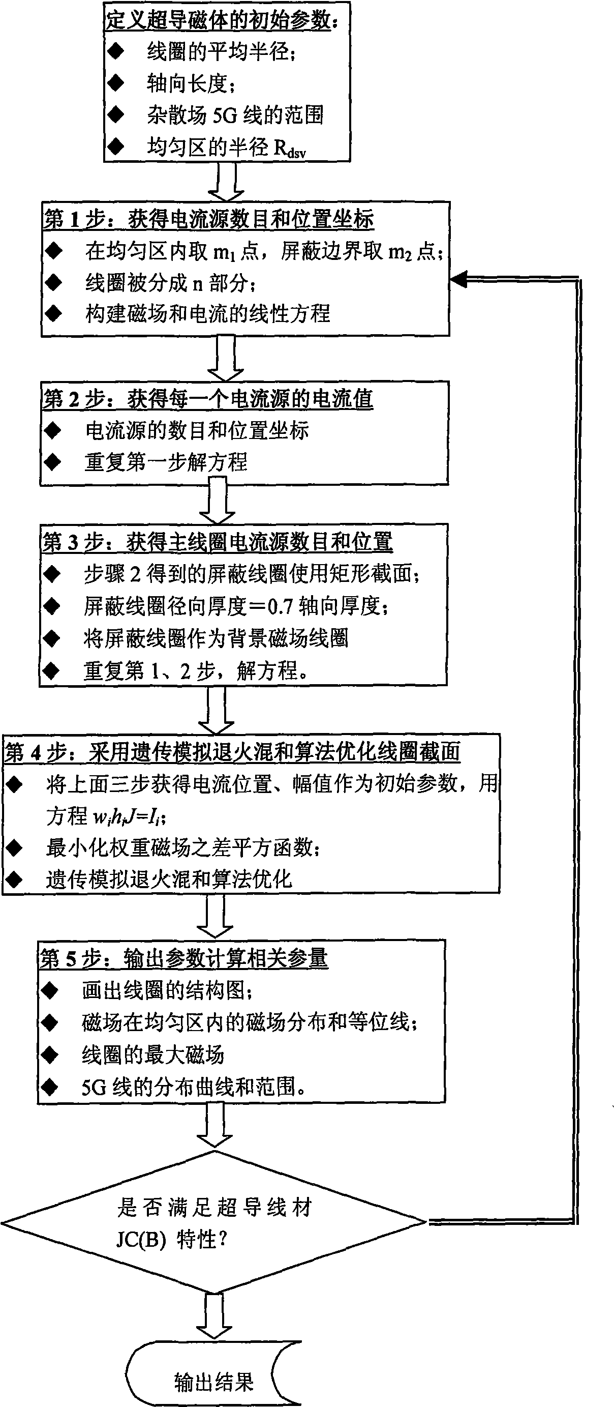
[0080] figure 2 Shown is the flow chart of magnet design, such as figure 2 As shown, the following are the specific impleme...


PUM


Abstract

An optimal design method of a superconducting magnet used for a magnetic resonance imaging (MRI) device comprises the following steps: obtaining current distribution maps of a primary coil and a screened coil according to magnetically confined conditions and then obtaining the initial cross section of the screened coil based on the current distribution maps; with the magnetic field of the screened coil as a background magnetic field, obtaining the current distribution map of the primary coil again according to magnetically confined conditions, thereby obtaining the initial cross section of the primary coil; based on the initial cross sections of the primary coil and the screened coil, optimizing coil section parameters by adopting hybrid genetic algorithm of simulated annealing to obtain the optimal coil geometries. By the method, the primary and the screened coil can be simultaneously designed.

Description

Technical field [0001] The invention relates to a design method of a superconducting magnet used in a magnetic resonance imaging device. Background technique [0002] Magnetic resonance imaging (MRI) is a high-tech imaging based on the performance characteristics of biological magnetic nuclei (hydrogen nuclei) in a magnetic field. In the past two decades, with the development of magnet technology, engineering electromagnetic field inverse problems, superconducting technology, cryogenic technology, electronic technology, and computers, MRI technology has developed rapidly. With its own technical characteristics and functional advantages, MRI has become an indispensable modern diagnostic equipment in clinical imaging diagnosis. [0003] The magnetic resonance imaging (MRI) system is mainly composed of a magnet system, a spectrometer system, a computer system and an image display system. The magnet system is the most important and costly component of the MRI system. The most importa...

Claims


Application Information

Patent Timeline
IPC IPC(8): G01R33/38
Inventor 王春忠王秋良王厚生
Owner INST OF ELECTRICAL ENG CHINESE ACAD OF SCI
Why Eureka
Eureka Blog
Learn More