
Injection valves for direct injection

An injection valve, direct technology, applied in the direction of fuel injection pump, fuel injection device, special fuel injection device, etc., can solve the problem of insufficient flexibility

Inactive Publication Date: 2015-08-05
MAN ENERGY SOLUTIONS SA
View PDF7 Cites 0 Cited by
  • Summary
  • Abstract
  • Description
  • Claims
  • Application Information

AI Technical Summary

Problems solved by technology

The disadvantage here is that there is not enough flexibility, since the lift of the valve needle is only controlled by the pressure in the nozzle antechamber
High pressure and sub-lift in the nozzle antechamber cannot be combined

Method used


Image

  • Injection valves for direct injection
  • Injection valves for direct injection
  • Injection valves for direct injection

Examples


Embodiment Construction

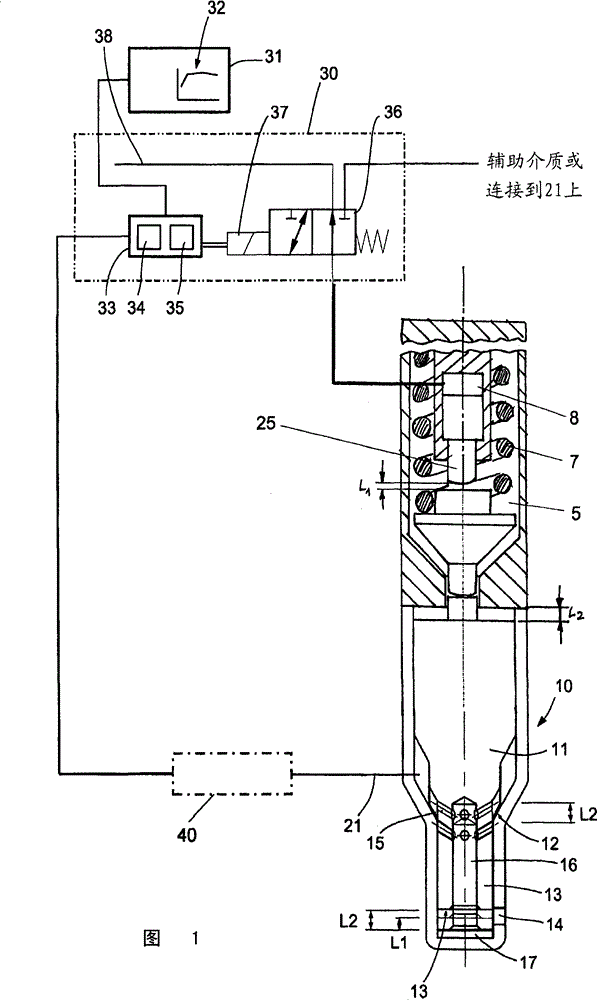
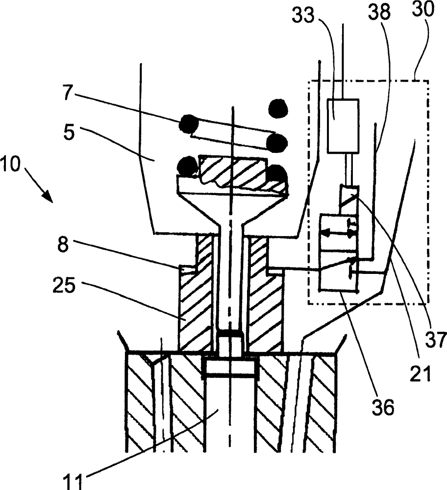
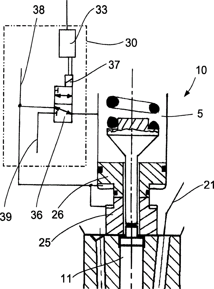
[0030] figure 1 An injector with a control device according to one embodiment of the invention is shown for the direct injection of fuel into a combustion chamber of a large diesel engine. Injection valve 10 has an axially displaceable valve needle 11 which can be mounted sealingly on a needle seat 12 . The valve needle 11 includes a needle tip 13 which completely covers the spray opening 14 in the region of the needle seat 12 when the valve needle 11 is in the position shown. In this position, fuel from injection pressure and volume flow source 40 cannot flow into injection chamber 17 of injection valve 10 via fuel line 21 .

[0031] Injection pressure and volume flow source 40 is only temporarily connected to fuel line 21 via a suitable switching mechanism.

[0032] If the valve needle 11 is raised from the needle seat 12 , the connection of the fuel line 21 to the injection chamber 17 of the injection valve 10 is opened. The fuel delivered through the fuel line 21 then ...


PUM


Abstract

The present invention relates to a injection valve for direct injection, wherein the injection valve is used to inject fuel directly in a burning compartment with a self-ignition internal combustion engine, and the valve is provided with a valve needle that can move long axial direction; the valve needle with a needlepoint can be put on a needle base hermetically; the needlepoint is set on location where the valve needle is in the needle base and covers a injection hole leading to the burning compartment. Furthermore, the injection valve also comprises a variable lift restrict device for regulating valve needle axial direction lift, wherein the needlepoint covered the injection hole.

Description

technical field [0001] The invention relates to an injection valve for the direct injection of fuel into a combustion chamber of a self-igniting internal combustion engine, which has an axially displaceable valve needle. The valve needle can be mounted sealingly on the needle seat and has a needle point which, in a position of the valve needle in the region of the needle seat, covers the injection opening leading to the combustion chamber. Background technique [0002] In direct-injection internal combustion engines, the structural design of the injection valves and the timing of the injection process influence the combustion process and thus also the efficiency and emission characteristics. [0003] DE 28 37 606 discloses a multi-jet valve of the above-mentioned type. The advantage of this type of injection valve is that there is little or no blind hole volume. Hydrocarbon emissions are significantly reduced compared to conventional injection valves. Through the above st...

Claims


Application Information

Patent Timeline
Patent Type & Authority Patents(China)
IPC IPC(8): F02M61/18
CPCF02M61/1846F02M61/184F02M2200/703F02M2200/701F02M63/0068F02M61/042F02M63/0026F02M61/161F02M45/12F02M61/1893F02M59/46F02M61/10F02M61/16
Inventor G·廷希曼
Owner MAN ENERGY SOLUTIONS SA
Learn More