
Liquid solid separating method for regenerating filtrate medium in filter

A filter medium and filter technology, applied in the direction of mobile filter element filter, filtration separation, separation method, etc., can solve the problems of increased labor intensity, high labor intensity, long non-working time, etc., and achieve management and maintenance work. The effect of small quantity, convenient replacement and high degree of automation

Active Publication Date: 2009-09-16
SHANGHAI RES INST OF CHEM IND
View PDF0 Cites 22 Cited by
  • Summary
  • Abstract
  • Description
  • Claims
  • Application Information

AI Technical Summary

Problems solved by technology

[0003] Generally, the liquid-solid separation method using pressure as the driving force needs to open the filter cylinder to regenerate the filter medium on the filter element during the filtration separation operation, which makes the non-working time in a filtration cycle even longer than the filtration time, and the operation is complicated. , greatly enhanced the labor intensity of workers
In addition, the existing method of liquid-solid separation under airtight conditions using pressurization as a driving force requires dismantling of bolts when replacing the filter medium, which is cumbersome to operate, labor-intensive for workers, and long non-working hours

Method used


Image

  • Liquid solid separating method for regenerating filtrate medium in filter
  • Liquid solid separating method for regenerating filtrate medium in filter
  • Liquid solid separating method for regenerating filtrate medium in filter

Examples


Embodiment 1

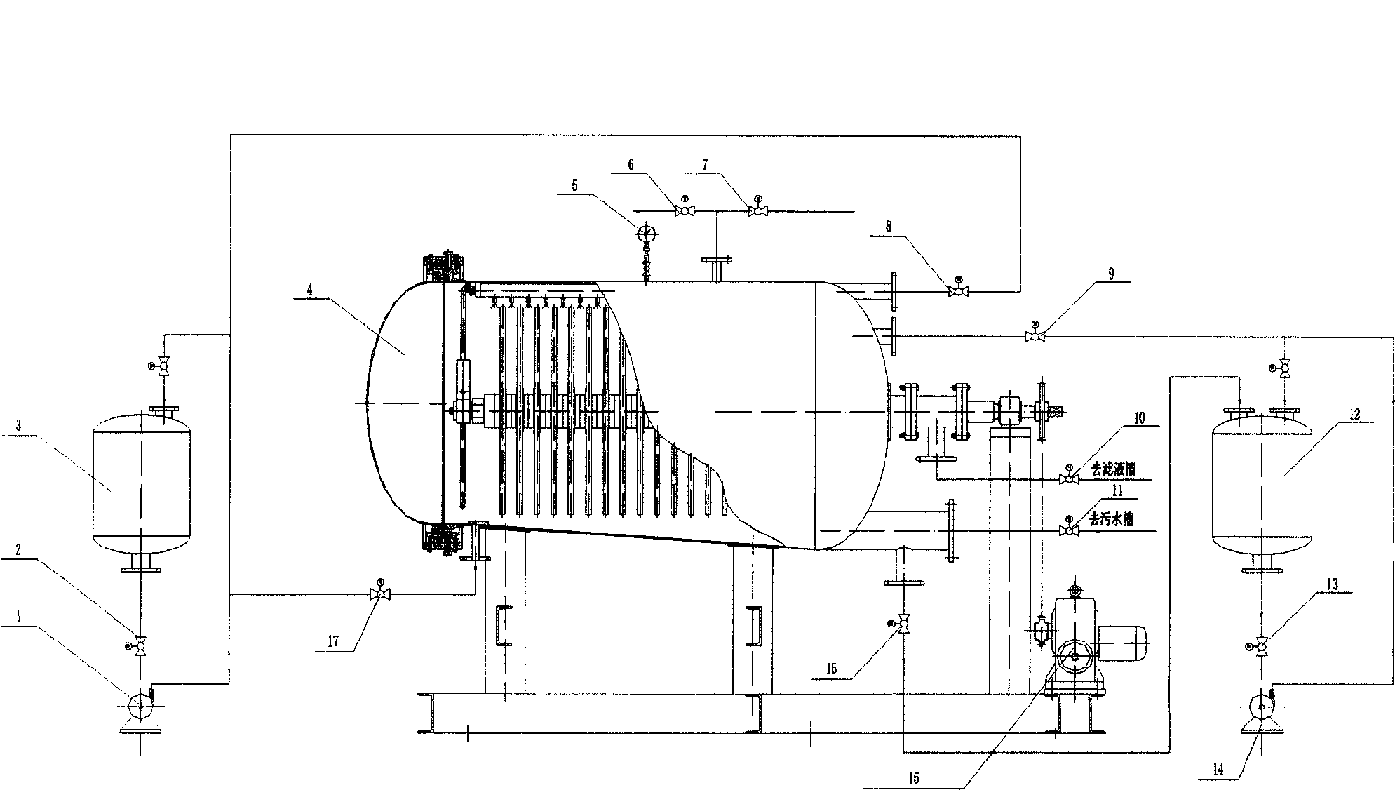
[0027] Such as figure 1 As shown, it is a schematic diagram of the liquid-solid separation process in which the filter medium is regenerated in the filter. Open the exhaust valve 6, the feed valve 9, the filtrate valve 10, and the slurry valve 13, and close the intake valve 7 and the sewage valve. 11. Filter disc rotation deceleration motor 15, discharge valve 16, flushing valve 17, pump the suspension containing fine solid particles to be separated in the slurry tank 12 into the new quick-opening pressurized leaf filter 4 by the pneumatic diaphragm pump 14 , after the filter 4 is filled with the suspension, close the exhaust valve 6 and continue to send the suspension to the filter for liquid-solid two-phase separation. After the pressure gauge 5 increases to 0.4MPa, close the pneumatic diaphragm pump 14 and the slurry valve 13. Open the intake valve 7 and the discharge valve 16. After the residual suspension in the filter 4 is emptied, close the discharge valve 16. After con...


PUM


Abstract

The invention relates to a liquid solid separating method for regenerating filtrate medium in filter, comprising the steps of: separating liquid solid two phases, removing filter cake, removing the filtrate medium and replacing the filtrate medium. Suspending liquid which is to be separated and includes fine solid grain is pumped into a novel quick opening type pressure leaf filter; under the function of the pressure of the pump, the solid phase grain is intercepted on the surface of the filtrate medium so as to form the filter cake; and the filtrate liquid passes through the filter cake and the filtrate medium and enters into the centre pipe of a filtrate disc so as to be discharged after being gathered. After the step of separating, a rotate positioning device drives a filter element to be rotated at an uniform speed, high-pressure water disassembles and cleans the filter cake which is covered on the filtrate medium by a nuzzle, and the filtrate medium is regenerated. The step of replacing the filtrate medium is carried out by fast switching the filter by a pneumatic control quick opening device. Compared with the prior art, the invention has the advantages of reasonable structure, safe operation, high work efficiency, high equipment automation degree, less management and maintenance workload, safe use, wide application range, etc.

Description

technical field [0001] The invention relates to a liquid-solid separation method, in particular to a liquid-solid separation method in which a filter medium is regenerated in a filter and pressure is used as a driving force to separate a suspension containing fine solid particles. Background technique [0002] The liquid-solid separation method using pressurization as the driving force is widely a non-thermal drying method. It is an important process in clean energy, three wastes treatment, water and water regeneration, and resource recycling. It is a new and expanded field in various fields today. It is an indispensable separation method in the industry, and is widely used in traditional industries, as well as emerging industries and high-tech industries such as electronic information, bioengineering, new energy, new materials, and environmental protection. With the development of industry, the suspension of liquid-solid separation is expanding; with the development of soci...

Claims


Application Information

Patent Timeline
IPC IPC(8): B01D33/21B01D33/48
Inventor 都丽红邓伯虎陈奕峰王士勇
Owner SHANGHAI RES INST OF CHEM IND
Learn More