
Picosecond pulse generator based on coplanar waveguide and trough line

A coplanar waveguide and picosecond pulse technology, applied in electrical components and other directions, can solve the problem that the pulse generator cannot meet the requirements of extremely narrow pulse width, and achieve the effects of low power consumption, adjustable input frequency and high repeatability

Inactive Publication Date: 2011-04-06
HARBIN INST OF TECH
View PDF0 Cites 0 Cited by
  • Summary
  • Abstract
  • Description
  • Claims
  • Application Information

AI Technical Summary

Problems solved by technology

[0004] The purpose of the present invention is to solve the problem that the existing pulse generator cannot meet the ultra-narrow pulse width requirement of ultra-wideband communication technology, and further provide a picosecond pulse generator based on coplanar waveguide and slot line

Method used


Image

  • Picosecond pulse generator based on coplanar waveguide and trough line
  • Picosecond pulse generator based on coplanar waveguide and trough line
  • Picosecond pulse generator based on coplanar waveguide and trough line

Examples


specific Embodiment approach 1

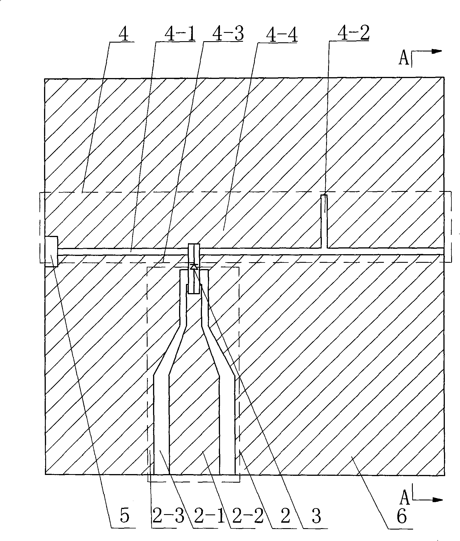
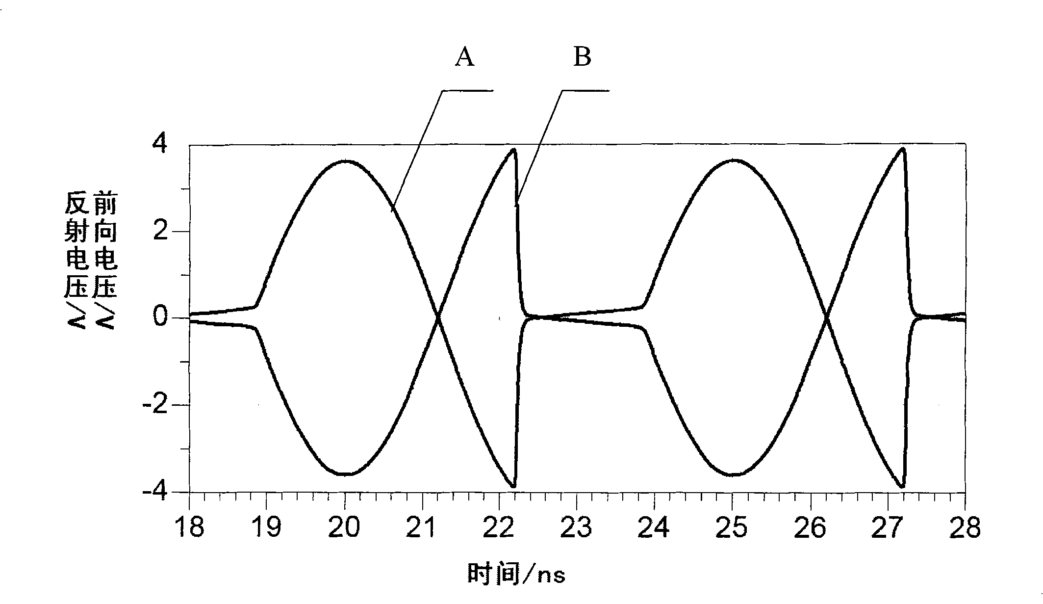
[0011] Specific implementation mode one: the following combination figure 1 , figure 2 , image 3 , Figure 4 with Figure 5 Describe this embodiment. This embodiment is composed of a dielectric substrate 1, a gold foil 6, an excitation signal coplanar waveguide 2, a step recovery diode 3, a slot line 4, and a thin-film absorption resistor 5. The surface of the dielectric substrate 1 is covered with gold foil 6, and the excitation signal The coplanar waveguide 2 and the slot line 4 are distributed on the dielectric substrate 1, the excitation signal coplanar waveguide 2 is composed of the first substrate 2-1, the input intermediate conductive strip 2-2 and the ground conductive strip 2-3, the slot line 4 is composed of the second Two substrates 4-1, terminal short-circuit groove 4-2, inner gold foil 4-3 and outer gold foil 4-4, one end of the input middle conduction band 2-2 is connected to the anode of the step recovery diode 3, and the end of the step recovery diode 3 ...

specific Embodiment approach 2

[0015] Embodiment 2: This embodiment differs from Embodiment 1 in that the surface area of ​​the dielectric substrate 1 is 6mm×6mm-8mm×8mm. Other composition and connection methods are the same as those in Embodiment 1.

specific Embodiment approach 3

[0016] Embodiment 3: This embodiment differs from Embodiment 1 in that the surface area of ​​the dielectric substrate 1 is 6 mm×6 mm. Other composition and connection methods are the same as those in Embodiment 1.


PUM


Abstract

A picosecond pulse generator based on coplanar waveguide and trough line belongs to the pulse generator. The invention aims to solve the problem that the prior pulse signal generator cannot meet the requirements of ultra wideband communication technique on the ultra-narrow pulse width. The invention is composed of a medium base plate, a gold foil, an excitation signal coplanar waveguide, a step recovery diode, a trough line and a film absorption resistor. The surface of the medium base plate is coated with the gold foil, the excitation signal coplanar waveguide and the trough line are distributed on the medium base plate and gold foil, the excitation signal coplanar waveguide is composed of a first base plate, an input intermediate conduction band and a grounding conduction band, and the trough line is composed of a second base plate, a terminal short circuit groove, an inner gold foil and an outer gold foil. One end of the input intermediate conduction band is connected to the positive electrode of the step recovery diode, the negative electrode of the step recovery diode is connected to the outer gold foil of the trough line, the left end of the trough line is equipped with the film absorption resistor, and the trough line at the right side of the excitation signal coplanar waveguide is equipped with the terminal short circuit groove. The invention can generate pulse of picosecond level.

Description

technical field [0001] The invention relates to a pulse generator, in particular to a picosecond pulse generator based on coplanar waveguides and slot lines. Background technique [0002] Ultra-wideband and ultra-wideband radar are the development direction of future communication and radar. In this type of communication and radar system, the baseband signal does not have to be modulated onto the carrier, but modulates the position of the nanosecond, sub-nanosecond (picosecond) pulse to achieve communication and target detection. Therefore, the signal bandwidth of this system can reach the order of several GHz, which can greatly improve the communication rate and the resolution ability of detecting targets, especially stealth targets. The picosecond pulse generator is the core component of the hardware in the above two systems. Existing pulse generators cannot meet the pulse width requirements of this ever-changing system. [0003] In microwave and millimeter wave broadba...

Claims


Application Information

Patent Timeline
Patent Type & Authority Patents(China)
IPC IPC(8): H03B28/00
Inventor 林茂六徐清华李娟张亦驰
Owner HARBIN INST OF TECH
Learn More