Eureka AIR delivers breakthrough ideas for toughest innovation challenges, trusted by R&D personnel around the world.

Supervoltage/extra-high voltage GIS isolating device

An isolation device and ultra-high voltage technology, which is applied in the direction of switchgear, switchgear setting, electrical components, etc., can solve the problem that the voltage transformer and lightning arrester must be withdrawn when the withstand voltage test is performed on the GIS for the first time. After the test is completed, the electrical performance Can not be verified, increase the installation workload and other problems, to achieve the effect of ensuring reliable separation and closing, fewer parts and simple structure

Active Publication Date: 2009-09-09
CHINA XD ELECTRIC CO LTD
View PDF0 Cites 13 Cited by
  • Summary
  • Abstract
  • Description
  • Claims
  • Application Information

AI Technical Summary

Problems solved by technology

As a result, when the insulation test is done after the installation is completed, or when the voltage transformer and arrester are routinely tested after running for a certain period of time, or when the GIS needs to be subjected to a withstand voltage test again due to maintenance, etc., the voltage transformer and arrester must be withdrawn from the test. Reinstall when done
The first impact is to increase the installation workload, and the second is that the electrical performance of the two cannot be verified. Once the electrified operation occurs, the loss caused by failure will be great

Method used


Image

  • Supervoltage/extra-high voltage GIS isolating device
  • Supervoltage/extra-high voltage GIS isolating device

Examples


Embodiment 1

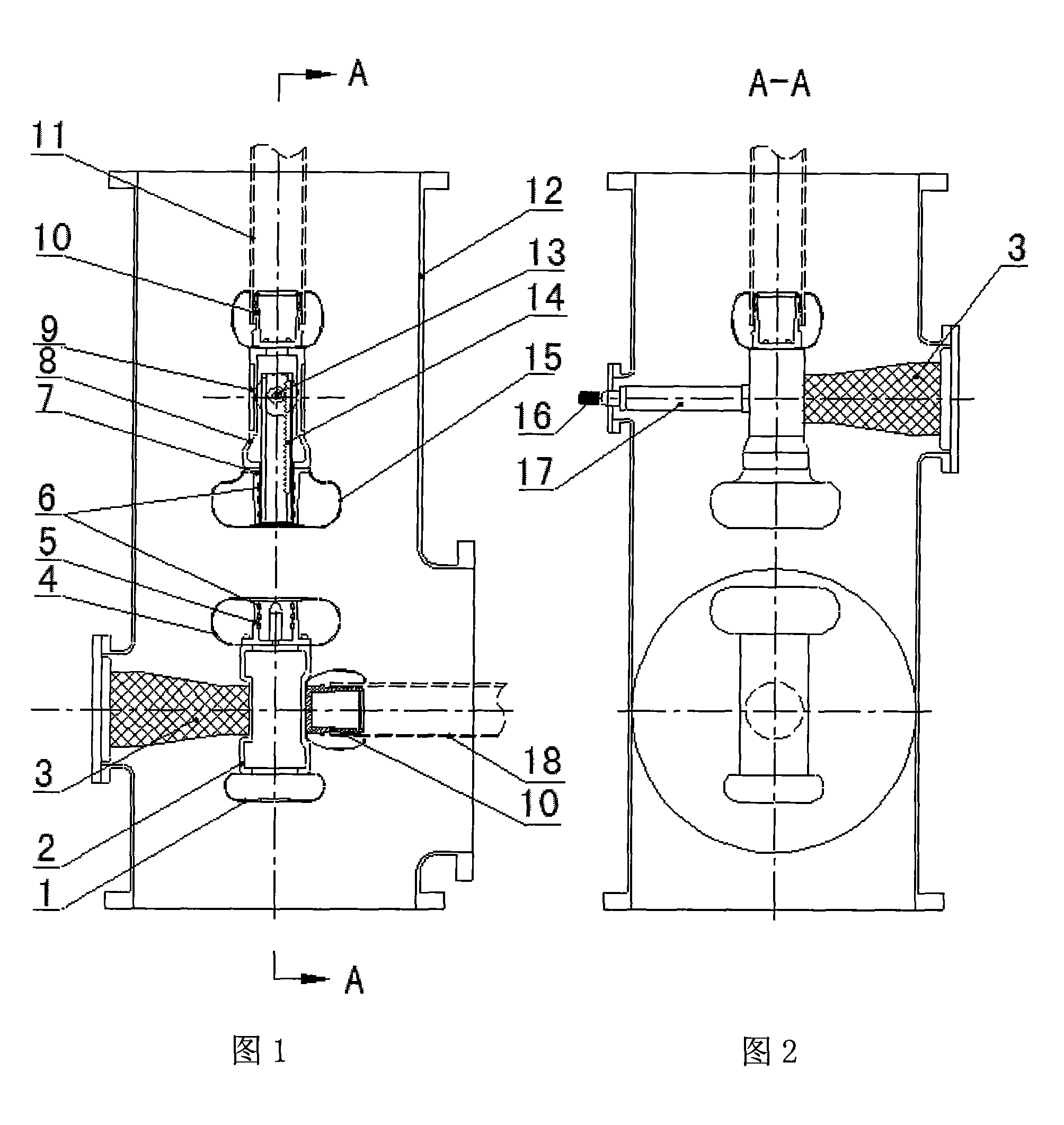
[0016] Such as figure 1 figure 2 As shown, an isolating device, its main body is electrically connected to the outside through conductors 11 and 18, and after being connected with other equipment, the interior is sealed in a SF filled 6 In the housing 12 of insulating gas, the circuit is connected or disconnected by whether the moving contact 14 with the rack and the spring contact finger 6 on the contact seat 5 on the static side contact or not.

[0017] The isolation device is arranged vertically. Due to the different functions of the contacts, the interior of the isolation device is divided into two parts: the dynamic side and the static side. In this embodiment, the dynamic side is placed on the upper part of the isolation device, and the static side is placed on the lower part of the isolation device. They are all fastened on the side wall of the housing 12 through the insulating support base 3 at an angle of 90°, and at the same time, they are electrically connected to...

Embodiment 2

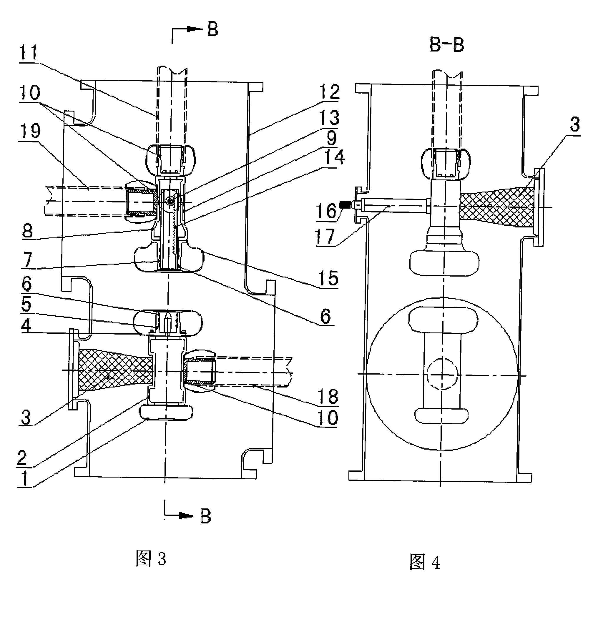
[0022] Such as image 3 Figure 4 As shown, another isolating device of the present invention differs from Embodiment 1 in that its moving side communicates with the outside through the two interfaces where the conductor 11 and the conductor 19 are located, the two conductors are perpendicular to each other, and the conductor 19 and the conductor 18 parallel to the center.

[0023] The working principle of this embodiment is: the isolating device realizes the conduction and disconnection of the circuit through the action of the moving contact 14 with the rack. At the closing position, the current is transmitted by conductor 11 and conductor 19, contact seat 10, moving side center conductor 8, moving side contact seat 7, static side contact seat 5, static side center conductor 2, and conductor 18, and to The shell 12 is well insulated from the ground; when the current flows through the central conductor 2, the contact base 10 and the conductor 18 on the static side, communica...


PUM


Abstract

The invention discloses a supervoltage / extra-high voltage GIS isolating device which comprises a shell, and a movable side part and a fixed side part which are arranged in the shell, wherein the two parts are fixed on the side wall of the shell by insulation supporting seats and connected with external devices by connecting conductors. The supervoltage / extra-high voltage GIS isolating device is characterized in that the movable side part is arranged at the upper part in the shell, the fixed side part is arranged at the lower part in the shell, and the movable side part and the fixed side part form a vertical structure. A moving contact in the movable side part is driven by an insulation operating rod and moves up and down along the direction consistent with the axes line of the shell, the insulation operating rod is led out of the chargeable shell by a rotating seal to realize that an inner contact operated manually moves away or contacts with a fixed side contact seat of the fixed side part to disconnect and connect an electric circuit; and the fixed side part can realize that two directions are connected to other GIS components or a bus.

Description

technical field [0001] The invention relates to an isolating device for super / ultra-high voltage gas-insulated metal-enclosed switchgear (GIS) of 800 / 1100kV voltage level. Background technique [0002] When designing switchgear in 800 / 1100kV substation, considering the cost-effectiveness problem, no isolating switch is installed at the connection of main equipment such as voltage transformer and lightning arrester. As a result, when the insulation test is done after the installation is completed, or when the voltage transformer and arrester are routinely tested after running for a certain period of time, or when the withstand voltage test is performed on the GIS again due to maintenance, the voltage transformer and arrester must be withdrawn and tested. Reinstall after you're done. The first impact is to increase the installation workload, and the second is that the electrical performance of the two cannot be verified. Once the electrified operation occurs, the loss caused ...

Claims


Application Information

Patent Timeline
Patent Type & Authority Applications(China)
IPC IPC(8): H02B13/035
Inventor 申春红史方颖穆双录
Owner CHINA XD ELECTRIC CO LTD
Why Eureka
Eureka Blog
Learn More