
Controllable light guide

A technology for light guides and components, applied in optics, nonlinear optics, instruments, etc., can solve problems such as coupling output efficiency limitations

Inactive Publication Date: 2009-08-26
KONINKLIJKE PHILIPS ELECTRONICS NV
View PDF1 Cites 12 Cited by
  • Summary
  • Abstract
  • Description
  • Claims
  • Application Information

AI Technical Summary

Problems solved by technology

[0006] Although the illumination system disclosed in WO 2004079437 provides controllable illumination of e.g. liquid crystal panels, the outcoupling efficiency is limited because the light management member is only sensitive to one polarization state

Method used


Image

  • Controllable light guide
  • Controllable light guide
  • Controllable light guide

Examples


Embodiment Construction

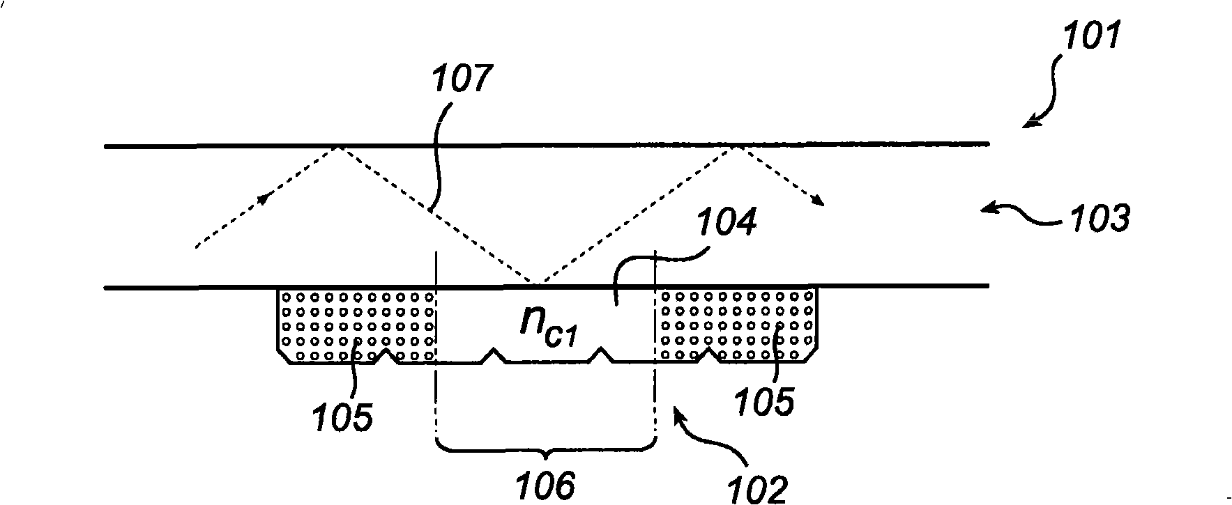
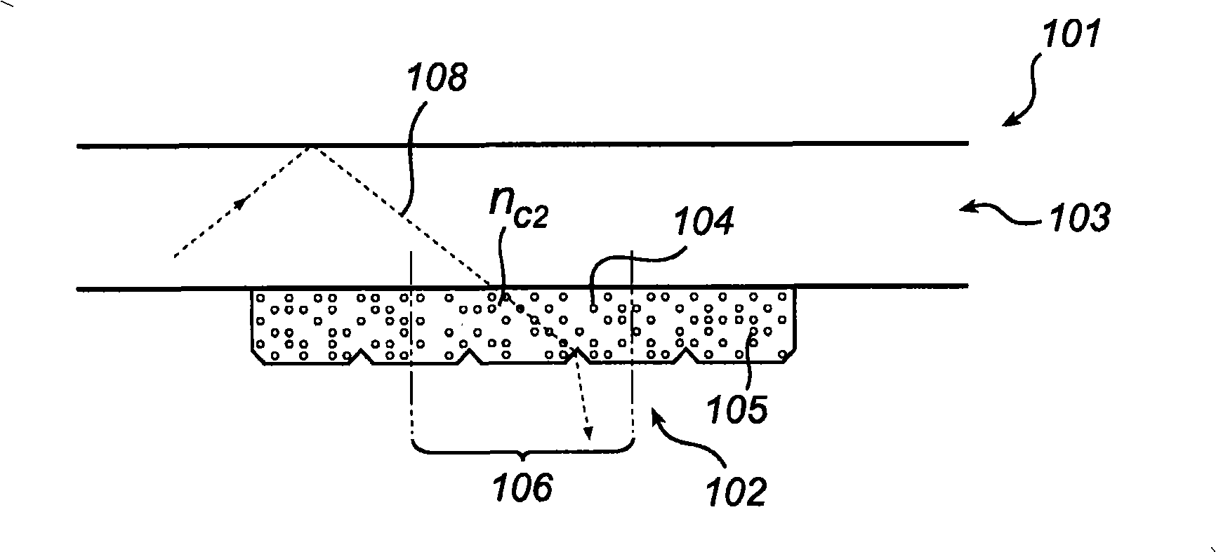
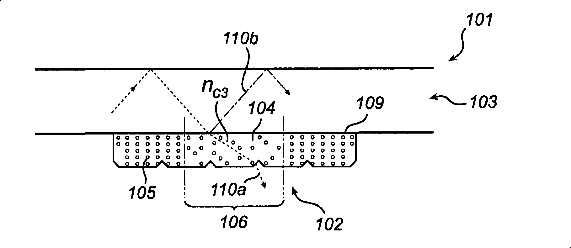
[0059] The invention will be described below primarily with reference to a planar controllable light guide comprising a light guide and a light modifying member having a plurality of positively charged particles suspended in a fluid having a lower refractive index than the light guide. The index of refraction and the index of refraction of the particles. It should be noted that this in no way limits the scope of the invention, which may equally apply to other configurations of steerable light guides, such as optical fibers and curved planar light guides. Furthermore, particles suspended in a fluid can be negatively charged, uncharged, magnetic or nonmagnetic. Of course, the refractive index of the fluid may be higher than that of the light guide and particles. In addition, an application example of an embodiment of the controllable light guide according to the invention is shown, wherein the controllable light guide is included in a backlight for a transmissive flat panel dis...


PUM


Abstract

A controllable light guide (101; 405) comprises a light guide (103) configured to guide in-coupled light through reflections of the light against a guiding boundary (109) of the light guide (103), and at least one light-modifying member (102; 201-202; 303-304; 414-416) arranged adjacent to the guiding boundary (109) of the light guide (103). The light-modifying member (102; 201-202; 303-304; 414-416) comprises a fluid (104) and a plurality of particles (105) distributed in the fluid. The light-modifying member is controllable between at least a first state having a first particle distribution resulting in at least a portion (106; 209, 210) of the light-modifying member (102; 201-202; 303-304; 414-416) having a first compound refractive index (rid), and a second state having a second particle distribution resulting in the portion (106; 209, 210) of the light-modifying member having a second compound refractive index (nc2). At least the second compound refractive index (nc2) is sufficiently high in relation to the refractive index of the light guide (103) at the guiding boundary (109) so as to allow at least partial outcoupling of light through a corresponding portion of the guiding boundary of the light guide.

Description

technical field [0001] The invention relates to controllable light guides, lighting devices and display devices comprising such controllable light guides. Background technique [0002] Various types of flat panel displays are currently used in a wide variety of applications, from mobile phone displays to large-screen televisions. While some types of flat-panel displays, such as plasma displays, include arrays of light-emitting pixels, most flat-panel displays have arrays of pixels that can switch between states but cannot independently emit light. Such flat panel displays include the ubiquitous LCD displays. In order for such flat panel displays to display images to the user, the pixel array must be backlit (in the case of a transmissive pixel array) or illuminated by ambient or front light (in the case of a reflective pixel array). [0003] Traditional backlights (and frontlights) include planar light guides into which light is coupled from a light source. One side of a ...

Claims


Application Information

Patent Timeline
Patent Type & Authority Applications(China)
IPC IPC(8): G02F1/13357G02F1/19G02F1/167G02F1/1335
CPCG02F1/167G02F1/133615G02F1/195
Inventor D·K·G·德博尔M·T·约翰逊S·J·鲁森达尔P·J·比斯朱H·J·科内利森
Owner KONINKLIJKE PHILIPS ELECTRONICS NV
Learn More