
Method and apparatus for bonding wafer

A chip and bonding technology, which is applied in the direction of electrical components, semiconductor/solid-state device manufacturing, circuits, etc., can solve the problems of low chip strength, poor chip-to-chip sealing, high damage rate, etc., to improve sealing, improve full dissolution and Uniform penetration and strength improvement effect

Active Publication Date: 2009-08-19
NANJING DEYAN ELECTRONICS
View PDF0 Cites 6 Cited by
  • Summary
  • Abstract
  • Description
  • Claims
  • Application Information

AI Technical Summary

Problems solved by technology

[0006] The above process defects: the bonding strength of the chip is small, the chip and the glue cannot be fully dissolved, the sealing between the chip and the chip is poor, and the damage rate of this product in subsequent processing is high

Method used


Image

  • Method and apparatus for bonding wafer

Examples


Embodiment 1

[0021] Embodiment 1, chip 25MHZ (chip model HC-49U / S)

[0022] 1. Configuration of glue for bonding wafers: 0.5kg of ozokerite 85, 0.3kg of rosin, and 0.5kg of hot melt adhesive are mixed and put on the heating plate in the aluminum pot for heating. The power of the heating plate is 1000W to make the ceresin and rosin . After the hot melt adhesive is fully melted, stir it. After stirring evenly, filter the glue solution with a 60-mesh metal filter and put it into a 30cm×50cm tray;

[0023] 2. Baking of the bonded wafer: put the wafer into the tray in the electric oven, the temperature of the electric oven is 170°C, and the baking time is 35 minutes;

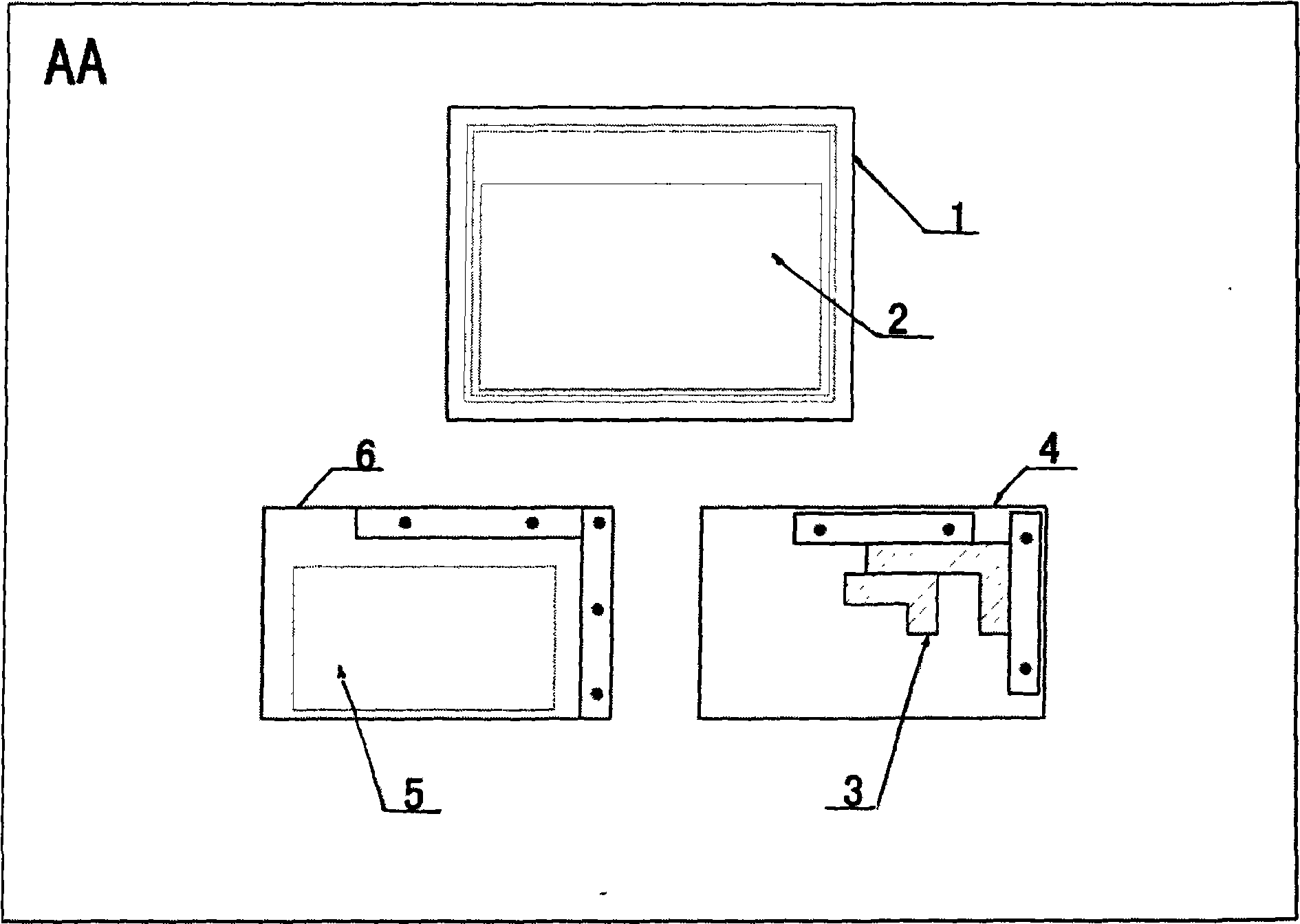
[0024] 3. The fixture frame 4 on the heating plate of the electric furnace B and the movable fixture 3 on the fixture frame 4 are preheated: the preheating temperature is 30°C;

[0025] 4. Put the configured glue on the heating plate of the electric furnace A and heat it. The temperature of the melted mixed glue is 140°C;

[00...

Embodiment 2

[0029] Embodiment 2, chip 20MHZ (chip model HC-49U / S)

[0030] 1. Configuration of glue for bonding wafers: 0.2kg of ozokerite 85, 0.12kg of rosin, and 0.2kg of hot melt adhesive are mixed and placed on a heating plate in an aluminum pot to heat. The power of the heating plate is 1000W, so that ceresin and rosin . After the hot melt adhesive is fully melted, stir it. After stirring evenly, filter the glue solution with a 60-mesh metal filter and put it into a 30cm×50cm tray;

[0031] 2. Baking of the bonded wafer: put the wafer into the tray in the electric oven, the temperature of the electric oven is 190°C, and the baking time is 45 minutes;

[0032] 3. Preheat the fixture frame for bonding wafers and the movable fixture on the fixture frame: the preheating temperature is 50°C;

[0033] 4. Put the configured glue on the heating plate of electric furnace A for heating: Put the prepared adhesive glue on the heating plate of electric furnace A, and the temperature of the mixed...


PUM


Abstract

The invention discloses a method for bonding wafers, and a device thereof. The method includes the processing steps of: preparing bonding wafer glue; baking wafers to be bonded; preheating a clamp frame of a wafer to be bonded and a movable clamp on the clamp frame; putting the prepared glue onto a glued iron plate of an electric cooker for heating; arranging the heated wafer on the heating glued iron plate so as to allow that the heating glue fully dissolves and permeates into the surface of each wafer; using a tool to rub the wafer so as to ensure even permeation on the surface of the wafer; putting a steelyard weight in the clamp frame and the movable clamp on the clamp frame and then extruding the clamp by two hands so as to remove unwanted glue, while a right angle is required to be tested to be 90 degrees plus or minus 1 degree by a try square and the planeness is required to be measured to be less than 0.2mm by a knife straight edge and a feeler gauge; and taking the wafer out of the clamp after the wafer is cooled at room temperature. The method has the advantages of improving the bonding strength of the wafer as well as full dissolution and even permeation of the wafer and the glue, enhancing the leak tightness between the wafers and increasing various quality indicators of final products while reducing damage to products in the follow-up processing.

Description

technical field [0001] The invention relates to a wafer bonding method and device thereof, belonging to the technical field of wafer bonding. Background technique [0002] The process method for wafer bonding in the prior art comprises the following process steps: [0003] 1) Configuration of bonding wafer glue: the weight ratio between the components is ozokerite: rosin: hot melt adhesive = 10:6:6; after mixing, put it in a steel pot and put it on the heating plate to make ozokerite and rosin After the hot melt glue is fully melted and stirred evenly, the glue is put into a 30cm*50cm tray with a 60-mesh metal filter; [0004] 2) Preheat the jig for bonding the wafer: put the used jig on the electric heating plate for preheating; [0005] 3) Use long tweezers to hold the ingot composed of evenly penetrated wafers, put it in the fixture, squeeze the fixture with both hands, and use a spatula to squeeze out the excess glue, and then press it flat and evenly. Finally, take i...

Claims


Application Information

Patent Timeline
IPC IPC(8): H01L21/50H01L21/56H01L21/00
Inventor 王玉香肖玉森
Owner NANJING DEYAN ELECTRONICS
Learn More